Reference no: EM133105530
Unit 3 Engineering Science - HNC ENGINEERING (Mechanical Engineering)
Characteristics and properties of Engineering Materials
Learning Outcome 1: Examine scientific data using both quantitative and qualitative methods
Learning Outcome 2: Explore the characteristics and properties of engineering materials
Assignment Brief:
Scenario: The following tasks take place in an area of land which is to be developed as a holiday activity park, catering for both land-based and water- based activities. There are various aspects and features of the site that need assessing and dealing with. This assignment presents some of those as engineering problems which need solving by the apprentices employed on site.
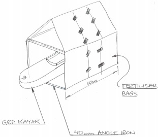
Question 1. As part of the water-sports operations, a fleet of second-hand kayaks is being purchased. They need to be stored temporarily out of sight and away from the effects of the weather. A variety of materials has been found on site and an apprentice has sketched a scheme:

The kayaks are constructed from glass reinforced plastic (GRP), the fertiliser bags are made of polyvinyl chloride (PVC) and the angle iron is low-carbon steel.
For each of the three materials, low-carbon steel, PVC and GRP, carry out research and describe:
- their manufacture
- the material structures produced ( atomic / crystalline / large scale )
- properties of the materials
- how these properties make them suitable for the purpose they have been used for in this assignment.
Question 2. With reference to the kayaks and storage facility above, carry out research and describe the possible ways the three materials may degrade:
• mechanically through normal use "wear and tear".
• mechanically through heavy, accidental impacts.
• through exposure to environmental conditions.
• from potential exposure to corrosive agents.
Question 3.

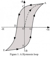
When the temporary shelter is eventually replaced with a permanent boathouse, a mains power supply is to be installed and LED lighting provided, using a transformer that was also located in the store. A supplier's handbook for the transformer has been found but with pages missing, including one to explain figure 1 shown above, which links to efficiency and losses in the iron core material used to manufacture the transformer.
Carry out research and explain what the diagram shows. Use the letter labelled points to assist you, but the explanation must go further than simply listing these.
Describe how the diagram would inform you as to whether the iron core material is suitable for transformer construction.
Question 4(a). Apprentices were asked to carry out tests on the shelter frame angle iron material - it was suspected to be carbon steel, AISI 1006 grade. Test pieces were taken to a local workshop equipped with Hounsfield Tensometer and Vickers Hardness testing capability.
The test piece dimensions were:
100 mm long by 5 mm thick by 20 mm wide. The test results were:
Tensometer
|
Test
|
Yield Force/kN
|
Max Force/kN
|
|
1
|
21.0
|
35.0
|
|
2
|
20.5
|
33.0
|
|
3
|
20.4
|
32.5
|
|
4
|
21.6
|
30.0
|
|
5
|
21.5
|
34.5
|
In addition, during the test, it was noted that an applied load of 10.3 kN produced an extension of 0.05 mm.
Vickers hardness -
|
Test
|
Load/kg
|
Diagonal ave/mm
|
|
1
|
50
|
1.00
|
|
2
|
50
|
0.99
|
|
3
|
50
|
0.97
|
|
4
|
50
|
0.96
|
|
5
|
50
|
0.93
|
Using the test data, determine average values for the yield stress and ultimate tensile stress.
Calculate values of Young's Modulus and Vickers hardness for the metal.
With reference to suitable engineering material properties databases, obtain quoted/published values for those that you calculated from the test data, and construct a comparison table. Justify whether the tested metal material is likely to be carbon steel AISI 1006 grade.
Question 4(b). Similar tensile tests were carried out on sample strips of the plastic roofing material in an attempt to confirm that it is PVC.
The test piece dimensions were:
300 mm long by 1mm thick by 40 mm wide. The Tensometer test results were:
|
Test
|
Yield Force/N
|
Max Force/N
|
|
1
|
1650
|
1850
|
|
2
|
1700
|
1900
|
|
3
|
1450
|
1650
|
In addition, during the test, it was noted that an applied load of 400 N produced an extension of 1.0 mm.
Using the test data, determine average values for the yield stress and ultimate tensile stress.
Calculate a value for Young's Modulus for the material.
With reference to suitable engineering material properties databases, obtain quoted/published values for those that you calculated from the test data, and construct a comparison table. Justify whether the tested material is likely to be PVC.
Question 4(c). Describe the SI system of "prefixes" and explain why they are used to express very large and very small values.
Use your values for Young's Modulus obtained in parts (a) and (b) to illustrate your explanation.
Explain how to handle quantities expressed in prefixes when performing calculations.
Demonstrate the consequences if this process is NOT followed by using your 4(a) calculation of yield stress for the steel material.
Question 5. It is proposed that the GRP kayaks be non-destructively tested using dye penetrant laboratory methods. Carry out suitable research to find out:
a) How the method would be used,
b) What information it would give.
c) Justify whether this is a valid approach for the GRP material of the kayaks.
d) Research at least two possible alternative, non-destructive methods, for testing the GRP material of the kayaks, and compare their effectiveness to the dye penetrant method.
Assignment - Characteristics and properties of engineering materials using scientific methods
Learning Outcome 1: Examine scientific data using computational methods
Learning Outcome 2: Explore the characteristics and properties of engineering materials
Scenario Update
As more kayaks are acquired, it is necessary to gain space by suspending some of them from the framework of the temporary shelter using elastic "bungee" type straps or similar.
Three large coils of potentially suitable elastic strap material have been located in a store shed. To confirm which of the strapping materials would be most suitable, load vs extension tests were carried out on 300mm length samples of each of them in the on-site workshop / laboratory.
Values for increasing and decreasing loads for each of the three samples are recorded in the tables below.
Question 1: You are required to write a laboratory report for the work carried out using a recognised scientific format.
Although you are not carrying out the practical work yourself, your report should include a description of how the work would be carried out.
The lab report must include suitable graphic presentation of the data obtained.
The discussion and analysis of the results must include aspects based on your own assessment of the results and comparisons of the graphs.
Your discussion should also be based on further research into what scientific and engineering information can be obtained from the graphs.
Remember that to complete the "scientific method", your discussion should include a "look forward" into possible future investigation / testing of the samples, and /or how the current testing method could be improved.
The load test results for the three samples are given on the next page:
Question 2: When you have completed the part 1 report, look through your assignment 2(a) for an aspect that resembles the results you have obtained for the load testing of the strapping materials. Compare the similarities and differences of the two aspects.
|
Loading (N)
|
Length of Sample 1 (mm)
|
|
Length of Sample 2 (mm)
|
|
|
Length of Sample 3 (mm)
|
|
|
|
0
|
300.0
|
|
300.0
|
|
|
300.0
|
|
0.25
|
300.2
|
|
300.5
|
|
|
300.6
|
|
0.50
|
300.6
|
|
301.0
|
|
|
301.3
|
|
0.75
|
301.1
|
|
301.7
|
|
|
302.2
|
|
1.00
|
301.6
|
|
302.4
|
|
|
303.1
|
|
1.25
|
302.4
|
|
303.2
|
|
|
304.2
|
|
1.50
|
303.2
|
|
304.2
|
|
|
305.5
|
|
1.75
|
304.2
|
|
305.4
|
|
|
306.8
|
|
2.00
|
305.6
|
|
306.6
|
|
|
308.2
|
|
2.25
|
307.7
|
|
307.7
|
|
|
309.2
|
|
2.50
|
314.0
|
|
308.6
|
|
|
310.1
|
|
Unloading
|
|
|
|
|
|
|
|
2.50
|
314.0
|
|
308.6
|
|
|
310.1
|
|
2.25
|
313.9
|
|
308.2
|
|
|
309.8
|
|
2.00
|
313.8
|
|
307.8
|
|
|
309.5
|
|
1.75
|
313.6
|
|
307.3
|
|
|
309.0
|
|
1.50
|
313.2
|
|
306.7
|
|
|
308.4
|
|
1.25
|
312.5
|
|
306.1
|
|
|
307.7
|
|
1.00
|
311.4
|
|
305.4
|
|
|
306.9
|
|
0.75
|
309.8
|
|
304.3
|
|
|
305.9
|
|
0.50
|
307.4
|
|
303.0
|
|
|
304.7
|
|
0.25
|
304.1
|
|
301.5
|
|
|
303.4
|
|
0
|
300.0
|
|
300.0
|
|
|
302.1
|
Attachment:- Engineering Science.rar