Reference no: EM132173233
Aim
The aim of this coursework is to assess student's knowledge on design of sewer system and stream flow measurement
Learning Outcomes
- To determine design flow and peak flow for a project.
- To understand the application of flow equations.
- To learn the components of urban drainage systems.
- To determine the stream flow using area velocity method.
Task-1: Assignment
PART 1
The students are required to explain the following terms related to urban drainage system using the figures along with the explanation.
1. Sewer Appurtenances
2. Sewer Corrosion
3. Catchment Area
4. Trunk sewer and Lateral sewer
5. Crown and invert level.
PART 2
The aim is to design sanitary sewer system to drain an urban area. Urban layout plan is provided with topographic levels. The main type of occupancy in an area comprises of residential units as shown in Figure 1. The sanitary sewer system is to be designed by considering the following details:
- Water consumption rate = 275 + (two last digit of student number) liter/head/day
- Infiltration rate=3 %
- Assume design period as 30 years and population growth rate as 4 %
- Each housing unit is an apartment building comprising of (Ground +2) floors and (5+ last digit of student number) persons in each floor.
- Follow natural drainage system to show direction of flow on the layout.
- Show individual connections to connect all the plots to the main sewer.
- Name each sewer and manhole using nomenclature of FS1, FS2, FS3... and MH1, MH2, MH3... respectively.
- Use the sewer sizes of 150, 200, 250, 300 mm......
- Use recommended ranges of gradients (I) for the design of sewers. The students are required to determine the following using data provided.
- Dry weather flow for each sewer
- Gradient for each sewer
- Diameter of each pipe
- Full section flow for each pipe (in m3/s) using Manning formula: QFS=23.97 * I1/2 * D8/3
(assume concrete sewers)
- Actual velocity in each pipe.
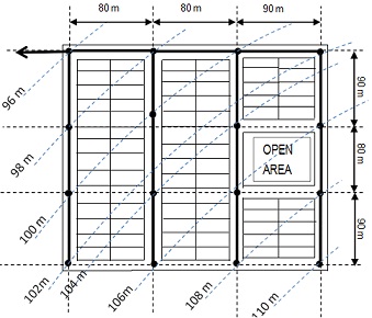
Figure 1
PART 3
Storm sewer system is to be provided to drain storm water to protect urban areas from flooding after episodes of rainfall. Storm sewer layout along with the contributing areas drained in specific sewer lines is shown in Figure 2. Design the storm sewer system for "gravity flow" assuming the following data:
- Assume C= 0.8 for all catchment areas
- Entry time to the pipe is the same for all sections Te= 6 min.
- All pipes are circular and made of concrete.
- Name each sewer and manhole using nomenclature of SS1, SS2, SS3... and MH1, MH2, MH3... respectively.
- Manholes are provided at heads of runs, at locations where there is changes in direction, changes in gradient, and changes in size, at major junctions with other sewers and at every 90 meter intervals.
On the basis of the given data determine the following:
- Length of each sewer using the given scale
- Runoff flow for each sewer using rational method
- Gradient for each sewer
- Diameter of each pipe
- Full section flow for each pipe (in m3/s) using Manning formula: QFS=23.97 * I1/2 * D8/3
(assume concrete sewers)
- Actual velocity in each sewer.
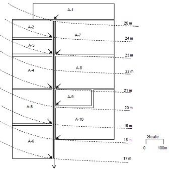
Figure 2
Task-2: Summative Class Assessment
- Class assessment on the topic ‘Stream flow measurement and application' will be conducted during the 8th teaching week with prior announcement.
- If a student does not attend the assessment, no replacement assessment will be scheduled for him/her and ZERO mark will be awarded for that assignment.
Attachment:- Assignment.rar