Reference no: EM132931327
300575 Networked Systems Design
Overview and Objectives
In this assignment you will design an enterprise scale network using the skills and knowledge gained in this unit and its prerequisites. This assignment is not a trivial task. To complete it as outlined with all the required documentation will be a significant task.
The assignment scenario describes in general terms, the network that is to be designed. Following the scenario, the assignment is broken into a number of sections (phases), each of these phases has a detailed list of requirements. It is important to read and understand each requirement to make sure that the assignment is completed accurately.
The following tasks are required to complete the assignment:
• Design the network using the diagram and accompanying requirements
• Simulate and test the network using the network simulator tool Cisco Packet Tracer
• Correctly configure EIGRP protocol
• Correctly configure VLANs and 802.1q trunking
• Correctly configure PPP and PPPoE
• Correctly configure DHCP
• Correctly configure GRE
• Correctly configure NAT and PAT
• Create and apply access control lists on the appropriate routers and interfaces
• Verify that all configurations are operational and functioning according to the scenario guidelines
• Provide documentation and configuration files as detailed in the following sections and phases.
Scenario
Introduction
Beresford is a company that has previous been based in the CBD of Newcastle. Recently, they have opened another site at Maitland which will be used to support a number of engineers. Because the engineers are frequently required at customer sites, they are expected to be working away from the Maitland office much of the time.
The business has grown rapidly; a proof of concept has been created, the infrastructure design has been planned and more engineers have been hired to scale the product. This new model will require a larger location for day-to-day management as well as a number of secure connections between home locations of newly appointed staff.
It is your group's task to analyse all the requirements and to develop a report that specifies the implementation of the requirements, offering realistic alternatives where possible (Final Report). This report will be used as the basis for the redeveloped structure, as Beresford grows.
Your group will be required to bench test the design to provide a "proof of concept" to ensure your group's solution will cater to Beresford's needs. This is an important step because it is essential to understand if the solution will work correctly before committing contractually to delivering this project. Bench testing in this case will be done with software emulation, Packet Tracer.
Requirements
Being a growing company, the initial network topology was just a simple router, switch and internet connection. With the rapid growth generated through hiring developers, Beresford has managed by purchasing additional switches and daisy chained them to create a single flat network.
Business requirements of Beresford:
• Scalable design which will facilitate business expansion.
• Seamless connectivity between their main campus at Newcastle (Newc1, Newc2 and Newc3) and the newly opened office at Maitland (Mait).
• Secure communication to cloud storage location (reached via ISP).
Beresford's Internet Service Provider (HunTel) will be providing a WAN solution and will be supplying your group with specific information and partial configuration to assist with bench testing.
Technical consultants have assisted Beresford in translating the above business requirements into the following sections, which contain technical requirements your group needs to incorporate into the solution.
Section 1: Basic Networking
Basic Configuration Requirements
• Configure device names as shown in the topology.
• Disable DNS lookup.
• Disable HTTP on all routers and switches.
• Enable SSH on all router and switches. Use the device name as the username and cisco as the password on all devices.
• Configure logging synchronous for the console line.
• Configure a MOTD banner to warn users that unauthorized access is prohibited.
• Device Security
o Encrypt the plain text passwords.
o Assign class as the privileged EXEC mode secret password.
Assign cisco as the console and VTY passwords for login.
• For testing purposes Beresford advises their WAN provider, HunTel, has set clock rate for all external WAN serial links to 128000 kbps.
• Configure the IPv4 and IPv6 addresses listed in the Addressing Table.
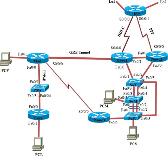
Topology Diagram
When the network design has been finalised a detailed topology diagram is required. The diagram will include but not be limited to the following:
• Internetworking devices and interface details.
• Link networks and IP address information.
• Routing Domains and static route details.
• Switching details and features e.g. STP, Channel Ports, VLAN information.
The topology diagram should be complete enough to allow a third party, for example a network contractor, to install and configure the network without any additional documentation.
Notes
Your group will be allowed to use this detailed topology diagram during the Demonstration.
Section 2: Network Addressing
IP Address Scheme
Beresford will be using the following addressing schemes:
|
Address Type
|
Address
|
Owner
|
|
IPv4 Private Address Allocation
|
172.20.0.0/19
|
Beresford
|
|
IPv6 Address Allocation
|
2001:172:20::/52
|
Beresford
|
|
IPv4 Public Address Allocation
|
210.50.0.0/28
|
Must be allocated across Newc1 and Newc2
|
|
IPv4 ISP Point-to-point Newc1 link
|
100.1.1.0/30
|
ISP
|
|
IPv6 ISP Point-to-point Newc1 link
|
2001:100:1:1::/64
|
ISP
|
|
IPv4 ISP Point-to-point Newc2 link
|
100.1.2.0/30
|
ISP
|
|
IPv6 ISP Point-to-point Newc2 link
|
2001:100:1:2::/64
|
ISP
|
|
ISP Lo1 for IPv4
|
55.55.55.55/32
|
ISP
|
|
ISP Lo1 for IPv6
|
2001:55:55:55::55/
|
ISP
|
|
ISP Lo2 for IPv4
|
66.66.66.66/32
|
ISP
|
|
ISP Lo2 for IPv6
|
2001:66:66:66::66/
|
ISP
|
The Data Centre provider has been asked to lease some of their public address space for Beresford's data centre infrastructure. HunTel will provide an internet tail (link) through serial connections to Newc1 and Newc2 and advertise this address space to the Internet. To achieve this there will be a static route implemented using the point-to-point link public address space provided in Table 2.
Network Requirements
• All routers, switches and PCs are dual stack devices.
• EIGRP router ID will come from the private IPv4 internal addressing.
• PPPoE links between all users on Eng Users networks and Mait will come from internal addressing.
Allocate address space and consider how this can be routed within the network.
• Ensure route aggregation has been built in to the addressing scheme for scalability.
• Gateway addresses will be assigned the first usable address in each subnet for both IPv4/6.
• Router interfaces for IPv6 will use static link-local addressing (to keep the addressing simple)
• Beresford's network manager, PCM, is physically connected to the switch SwM. PCM uses the last address on the Management VLAN.
Host Requirements
• Newcastle will use IPv6 addresses which are dynamically assigned through SLAAC.
VLAN Information
Subnetting using VLSM is required for network addressing scheme.
Site VLANs Required
Newc1, Newc2 and Newc3 Accounting/Marketing/Sales/Office
|
Site
|
VLANs Required
|
|
Newc1, Newc2 and Newc3
|
Accounting/Marketing/Sales/Office
|
|
Mait
|
Maitland Office / Engineering
|
|
Both sites
|
Native / Management / Blackhole
|
Table 3: VLAN Information List
Notes
The tables A.1 and A.2 must be completed for the Progress Report due in Week 5.
Warning
Network addressing scheme should take into account route aggregation (summarisation).
Addressing Requirements
|
VLAN
|
Host Requirements
|
Growth
|
|
Newc Accounting
|
40 Hosts
|
Yes
|
|
Newc Marketing
|
90 Hosts
|
Yes
|
|
Newc Sales
|
100 Hosts
|
Yes
|
|
Newc Office
|
250 Hosts
|
Yes
|
|
Management
|
5 Hosts (per site)
|
No
|
|
Mait Office
|
50 Hosts
|
Yes
|
|
Mait Engineering
|
30 Hosts
|
Yes
|
Table 4: Current Host Addressing Requirements
Beresford expects that it will have to provision for doubling of the sizes of most of its VLANs over the next two years.
Section 3: Switching Networks
Beresford is moving away from their ad-hoc switch design to a more hierarchical and scalable design. The deployment of the following technologies should "future proof" the business for further expansion as required.
VLAN Requirements
• Switch access ports allocation is three ports per VLAN per switch.
• Assign VLAN 199 as the Management VLAN and Native VLAN.
• Any unassigned ports are to be placed into an unused and non-routed VLAN (also referred to as a BlackHole VLAN (VLAN 668) (i.e. next door to the Devil). Additionally, these ports should be disabled and the VLAN deleted.
• Allow only configured VLANs to be permitted on trunk links.
Switching Technologies
• Enable rapid-PVST+ on all switches.
• Manipulate Spanning Tree to load balance VLANs between all HQ switches.
• Implement EtherChannel between SwM and SwB. Justify your choice of EtherChannel method chosen.
• Implement First Hop Redundancy (FHR) using HSRP on Newc1 and Newc2. Load Balance Active and
Standby between these two physical routers.
Section 4: Network Routing
With the flexible IP address scheme created for Beresford, integration of the newly created environment using EIGRP will be deployed throughout its organization.
Routing Requirements
• Inter-VLAN Routing: Layer 3 routing at the Newcastle virtual router and router-on-a-stick at
Maitland.
• Summarisation to be implemented where possible with EIGRP.
• EIGRP Router IDs allocated from internal IPv4 addressing.
• For best practice and security reasons, unnecessary routing updates shall be prevented.
EIGRP Requirements
• Configure EIGRP throughout the routing domain.
• EIGRP routing updates and adjacencies between Newcastle and Maitland must occur over the GRE tunnel.
Warning
A functional GRE tunnel (in Section 6) is required for exchanging EIGRP routes successfully between Maitland and Newcastle. (While preparing your implementation, you may wish to use static routes temporarily, for testing purposes).
Section 5: Security and Monitoring
The following security measures are to be imposed, for both IPv4 and IPv6 addresses:
• Users on the Sales VLAN are not to be permitted to access any networks outside their own VLAN.
• Users on the Engineering VLAN are permitted to reach only the Internet and users within their VLAN.
• PCM is the network manager's PC. Ensure that it is the only device which can manage Beresford's
routers and switches
PCM should maintain a log file of all security violations. Unauthorised attempts to connect to either switch
SwT or switch SwB should be reported to PCM.
Section 6: WAN
For redundancy, an alternate link to ISP is required from Newc2 Router. Because HunTel cannot guarantee that its interface on this link will be provided by a Cisco router, Beresford will have to use PPP with CHAP authentication on this link.
To improve load balancing, this link must be used for those VLANs for which Newc2 is the Active router. Appropriate floating static and default static routing is required for this implementation. The two loopback addresses on ISP will represent cloud storage, and for this exercise, it is sufficient that all internal hosts can successful ping these two loopback addresses using both IPV4 and IPv6 addresses.
To simplify later integration of the Newcastle and Maitland sites, a Virtual Private Network (VPN) is planned. Even though the link between the two sites is a private network, a business requirement dictates the tunnel must be encrypted to ensure sensitive data cannot be intercepted by any means.
Your group will demonstrate VPN technology using a GRE tunnel connecting routers Newc1 and Mait. Thus, addressing this key business requirement, and solving a complex design issue but more importantly instilling confidence through your technical ability.
To provide home user access PPPoE will be implemented. For the demonstration a single PPPoE connection is required. However, the addressing and routing should be designed to allow 10 simultaneous PPPoE connections. (In Figure 1, this functionality can be demonstrated by PCL which is connected to router Cess - representing the potential for a number of PPPoE connections at Cessnock and other areas.)
To provide internet connectivity and public addressing for webservers Network Address Translation (NAT)
needs to be configured on the border routers at Newcastle. Public addressing has been leased (see Section
2) and subnetted from the Data Centre's public address blocks. This address space will be advertised to the Internet by HunTel and traffic redirected back to Beresford's network via floating static routes.
WAN Requirements
- Statically assign IP addressing for the connecting router's interfaces.
Site to Site Connectivity
- The point-to-point VPN tunnel will use private addresses and will terminate at Newc1 and Mait.
- Enable EIGRP routing to exchange routes over the tunnel.
- Ensure traffic is flowing through the tunnel interfaces (not the carrier link).
Network Address Translation (NAT)
- All devices within Beresford's network are expected to have internet connectivity using the given address range with overloading.
- Internet is to be simulated by a loopback interface on the ISP router.
Attachment:- Networked Systems Design.rar