Reference no: EM132979923
Question: A 7-segment display is an arrangement of seven LEDs (labelled i-o), as shown here. Arrays of such displays are commonly used to display characters in remote controls, blood pressure monitors, dishwashers, and other devices. Each LED can be on or off, but in most applications, only a small number of on/off combinations are of interest (such as the 10 combinations that allow the display in a digit in the range 0-9). In that case, the display can be con- trolled through a small number of input wires. For example, four input wires provide 24 input combinations, enough to cover the ten different digits.

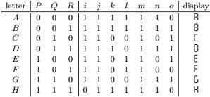
Here we are interested in using a 7-segment display for some uppercase letters. We want it to be able to show eight different letters, namely A, B, C, D, E, F , G, and H. For example, to show A, all the display segments, except o, should be lit up, giving the pattern . In detail, we want the eight different letters displayed as A,B, C, D, E, F, G, and H, respectively. Since there are eight letters, we need three input wires, modelled as propositional variables P , Q, and R. We will need to decide on a suitable encoding of the eight letters. One possibility is to let A correspond to input 000 (that is, P = Q = R = f ), B to 001 (that is, P = Q = f and R = t), and so on. If we do that, we can summarise the behaviour of each input combination in the table below:

Each of the seven segments i-o can be considered a propositional function of the variables P , Q, and R. This kind of display can be physically implemented with logic circuitry, using circuits to implement a boolean function for each of the outputs. Here we assume that only three types of logic gates are available: An and-gate takes two inputs and produces, as output, the conjunction (∧) of the inputs. Similarly, an or-gate implements disjunction (∨). Finally, an inverter takes a single input and negates it (¬). We can specify such a circuit by writing down the Boolean equations for each of the outputs i-o. For example, segment i is turned off (is false) exactly when the input is 111. So, i can be captured as ¬P ∨ ¬Q ∨ ¬R.
For efficiency reasons, we often want the circuit to use as few gates as possible. For example, the above equation for i shows that we can implement this output using five gates. But i = ¬(P ∧Q∧R) is an equivalent implementation, using only three gates. Moreover, the seven functions might be able to share some circuitry. For example, if we have already implemented a sub-circuit defined by u = Q ∧ R (introducing u as a name for the sub-circuit), then we can define i = ¬(P ∧ u), and we may be able to re-use u while implementing the other outputs (rather than duplicating the same gates). In some cases it may even be feasible to design a circuit that is not minimal for a given function, but provides a minimal solution when all seven functions are designed.
Task. Design such a circuit, using as few gates as possible. You can define any number of sub-circuits to help you reduce the gate count (simply give each a name).
# An example of a set of equations in the correct format: i = -Q R + Q -R + P -Q -R
j = u + P (Q + R) k = P + -(Q R)
l = u + P i u = -P -Q
# u is an auxiliary function introduced to simplify j and l