Reference no: EM132492707
Communication Assignment -
Question 1 - This is to design a PSK (phase shift keying) system and assess the effects of number of constellation as well as communication channel.
(i) Use Simulink to design a Binary PSK (BPSK) communication system as in Figure 1.

Use random binary source generator (you may use the source setup in your Lab 5 - Extra experiment) and AWGN (additive white Gaussian noise) as your channel effect. Use oscilloscopes and constellation maps to inspect the signals at right points of the system. Increase the noise level, draw the bit error rate (BER) versus signal to noise ratio (SNR), and specify at which noise level the demodulator is not able to recover the original signal accurately anymore. Draw your schematic and provide the constellation maps together with the input and output binary signals.
(ii) Use QPSK instead of BPSK in part (i). Demonstrate the results and compare it with those of BPSK. You may use the symbol rates similar to those suggested in the lab exercises.
Question 2 - This is the extension of Q1. Use MATLAB and Simulink.
(i) In Figure 1. Use QPSK as your PSK modulator and replace the AWGN channel with a Rayleigh fading channel with 5 paths. Increase the fading level and specify at which fading level the demodulator is not able to fully recover the original signal anymore.
(ii) Replace QPSK with 64-QAM, see the results, and explain the advantages and disadvantage of this system over BPSK and QPSK. Explain the differences between the two systems in terms of type of the channel and the level of noise and fading they can tolerate.
For each case register the numbers you used as gains, delays, and maximum Doppler frequency and provide the settings you have chosen/made for any of the Simulink module blocks. Also, provide the constellations diagrams before and after the channel and the signals in the inputs and outputs.
Question 3 - Here, an OFDM system is designed and evaluated. Using Simulink, setup the system according to Figure 2.
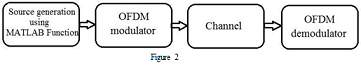
Select a four-path channel with discrete delays (0:4:12)*1e-6 Sec, average path gains of [0 -3 -6 -9] dB and sample rate of 50 KHz. Explain what the four paths can be related to.
(i) Use "MATLAB Function" in Simulink to generate a random complex-valued input as Data = complex(rand([256 4 1]), rand([256 4 1])); Explain what the digits 4 and 1 in the Data argument refer to.
(ii) Apply orthogonal frequency division modulation/multiplexing (OFDM) to Data. Consider a Rician fading channel between the transmitter and the receiver. To evaluate the system for different fading levels, use constellation maps (why?) before the modulator and after the demodulator.
(iii) Explain how Doppler shift relates to mobile systems. Change the Doppler shift value in the "Channel" block from 0 to 150 Hz and compare the results for different settings.
Hint: For the OFDM modulator and demodulator you may choose discrete Fourier transform (DFT) length 267, number of guard bands [6; 5], and cyclic prefix length 16.
(iv) Change the data to
Data = complex(randn([256 10 2]), randn([256 10 2])
Explain what the arguments [256 10 2] refer to and repeat (ii) and (iii). Can you still use constellation maps to view the data? Why? Try to find and explain a way to view and compare the input and output.
There might be few more variables to set for your Simulink modules/blocks. In order to do that refer to the settings you made during the lab sessions or decide yourself. Make sure you explain about your choices in each question/part.