Design a bias network for an RF amplifier

Assignment Help Electrical Engineering
Reference no: EM131502359

1. Design a third order Butterworth low pass filter using micro strip lines with Richard's Transforms and Kuroda Identities for a cutoff frequency of 2.4 GHz. Draw the final schematic in terms of normalized transmission line impedances and lengths. Simulate using ADS and show S-parameter plots to 3.5 GHz. Place Marker at 2.4 GHz.

2. Impedance match a complex load of ZL = 25+ j15 W to a 50 W source impedance using a three element L-C matching pi-type network with one series inductor. Remember to perform conjugate matching for maximum power transfer. Determine the component values for operation at 500 MHz. Show your work by hand using the Smith Chart. Simulate using ADS and include results of S-parameters from 250 MHz to 750 MHz; Place marker at 500 MHz.

3. Determine the ABCD matrix for the matching network of problem #2. What is the transfer function of the circuit?

4. Design a bias network for an RF amplifier (common-emitter or common-base) using a BFR92 npn BJT. The transistor bF = 92 and the bias point is VCE = 10 V, and IC = 20 mA. Let Vcc = 24 V. Show the schematic of the circuit.

5. The BFR92 transistor with common-emitter S-Parameters for VCE=10V and IC=20 mA given as:

1828_Figure.png

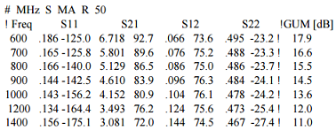
Using the bias point specified in problem (4), design a 1GHz narrowband amplifier using a PCB make of G10 or FR4 material. Use single stub tuners for input and output matching to 50 W. What is the voltage gain of the amplifier? Please show all work using Smith.

Charts and hand calculations, and the circuit diagram. Simulate using ADS and show Sparameters between 750 MHz and 1.25 GHz. Place a marker at 1 GHz.

6. Design an L-C High Pass Chebyshev Filter with 3 dB ripple for a cut-in frequency of 330 MHz with a stop band attenuation of 18 dB at 250 MHz. The system impedance is 50 W. Show all component values. What is Q of the circuit? Show S-parameter results for the filter using ADS from 100 MHz to 700 MHz.

Need full and detailed steps for the solutions in the assignment problems.

Reference no: EM131502359

Questions Cloud

Underlying causes of the great depression : What were the differences and the similarities in the underlying causes of the great depression and the great recession?
Why is it upward sloping : Derive the LM curve. Why is it upward sloping? Under what conditions will it be vertical and horizontal?
Economy using the money multiplier model : Explain how increase in required reserve may adversely affect the economy using the money multiplier model.
Write a sample portion of an emergency plan : write a sample portion of an emergency plan for that section for your hometown or another municipality of your choice.
Design a bias network for an RF amplifier : Design a bias network for an RF amplifier (common-emitter or common-base) using a BFR92 npn BJT
What is the equilibrium interest rate : Graph the supply and demand for real money balances. What is the equilibrium interest rate?
What behaviors would someone with strong self-awareness : What behaviors would someone with strong self-awareness demonstrate within the context of leading and managing groups? Provide an example.
Latter product management team : Utilizing the concept of opportunity costs, why would the latter product management team be less than receptive to the all-day breakfast menu?
Containing three tacos and a medium drink : While waiting in line to buy two tacos at 75 cents each, and a medium drink for 80 cents, Jordan notices that the restaurant has a value meal containing.

Reviews

Write a Review

Electrical Engineering Questions & Answers

  Design a 4-bit synchronous up-down counter

Design a 4-bit synchronous up/down counter using T flip-flops. The circuit has one input up' /down such that input 0 means count up and input 1 means count down. up' is "up" with a bar over it

  What is the total positive ionic charge in depletion width

A silicon abrupt junction, approximated by a step junction, has a doping of NA= 5 x10¹⁵/cm3 and ND= 1015/cm3 and a cross-sectional area (A) of 10-4cm2. Assume the depletion approximation, VA=0, and ni=1010/cm3 to: a. Calculate Vbi.

  Calculate the copper and core losses in transformer

A 150-MVA 15/200-kV single-phase power transformer has a 0.018ohm resistance and a 0.075ohm reactance. The magnetizing impedance is j80 per unit. a.) Find the equivalent circuit referred to the low-voltage side of this transformer.

  Formulate node voltage equations for the circuit

Formulate node-voltage equations for the circuit in Figure.- Solve for vx and ix when R1 =1kΩ, R2 = 1:5 kΩ, R3 = 500 Ω, R4 =2kΩ, Rx = 100 Ω, and vS = 15 V.

  Determine the current in the cable

Determine the current in the cable, the losses in the cable and the supply voltage - Each core has a resistance of 0.01 D.

  Draw three equivalent branches for the given branch

Using the substitution theorem, draw three equivalent branches for the branch a-b of the network of given figure b.

  How to find out the parameters need for the lab

The first stage is a common-emitter amplifier and the second stage is a common-collector stage. You should use one npn (2N3904) and one pnp transistor (2N3906) to design the circuit to meet the design criteria. Use the transistor datasheets to fin..

  Estimate the ratio of powers generated by the same speed

Suppose a turbine is used for generating electricity, estimate the ratio of powers generated by the same speed water and air. (Water density=1g/cm3, air density =1.2kg/m3)

  Sketch a clocked cmos domino logic circuit

Sketch a clocked CMOS domino logic circuit. - Assume that both the variable and its complement are available as input signals.

  What is the turns-ratio of the transformer

Assume a line voltage of 2,400 volts is connected to the primary of the three-phase transformer and the line voltage of the secondary is 240 volts. What is the turns-ratio of the transformer?

  Check whether the number of dffs inferred by the compiler

Recompile the code for N = 4 and simulate it using the same stimuli of figure 11.13a, checking whether the same results are obtained here.

  Determine norton current and source resistance

A particular signal source produces an output of 30 mV when loaded by a 100-k ohm resistor and 10 mV when loaded by a 10-k ohm resistor. calculate the thevenin voltage, Norton current, and source resistance.

Free Assignment Quote

Assured A++ Grade

Get guaranteed satisfaction & time on delivery in every assignment order you paid with us! We ensure premium quality solution document along with free turntin report!

All rights reserved! Copyrights ©2019-2020 ExpertsMind IT Educational Pvt Ltd