Reference no: EM133256610
Programmable Logic Controllers
Assignment Theory
Question 1. (a) By using a truth table or otherwise, show that the expressions below are equivalent
(AB‾ + BC‾ + AC‾)‾ = ABC
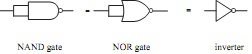
(b) Show by plotting truth tables that the following 2 input gates are equivalent to an inverter
Question 2. Draw the logic circuit to represent the following Boolean expression using only two input NAND gates.
F = ((AB.BC‾)‾.(A‾C)‾)‾
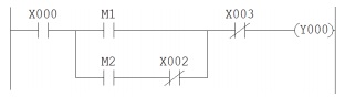
Question 3. Write down the Boolean expression for the following ladder diagram. X denotes a switched input, M represents an internal relay contact and Y000 is a motor contact.
Question 4. (a) Convert the following Hex numbers to binary and add them. Express your final answer in HEX
2A7E + 45CB
(b) Write down the 2's complement of the following binary number
10110000
(c) Convert the following numbers to binary and evaluate using the 2's complement method. Leave your answer in binary form.
68 - 145
(d) Write down the BCD form of decimal 936.
Question 5. Describe two advantages of a PLC based system over a purely relay based one.
Question 6. Referring to the opto-triac output circuit shown below.
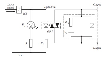
Given the following parameters
Logic voltage = 3.3V
D1 forward voltage drop = 1.8V D1 operating current = 10mA
Opto-triac minimum operating current 2mA Opto-triac LED forward voltage drop 1.6V
Calculate suitable values for R1 and R2, show all your working.
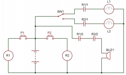
Question 7. Convert the following circuit diagram to PLC ladder logic, giving full list of I/O and any internal logic used. Describe the operation.
Question 8. Explain the basic operation of a PLC scan cycle.
Question 9. (a) Describe the operation of the ladder circuit shown below. The ladder uses the Mitsubishi standard of M for internal relays, Y for external output and T for timer.
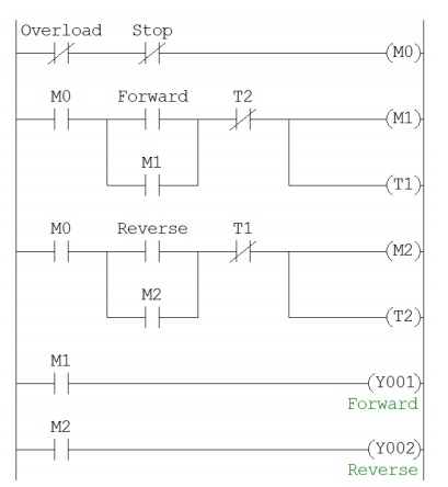
(b) What type of application could this circuit be used for?
(c) What is the purpose of the timers?
Question 10. What is the difference between opcodes and operands?
Question 11. (a) An A/D conversion has an 8 bit resolution and an input range of 0~5V. A second convertor has an input range of 0~24V and a 10 bit resolution. Calculate the digital output value in Hex that will represent 3V in both cases.
(b) State which of the two convertors in (a) is more accurate and explain why.
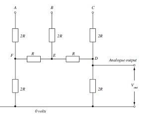
Question 12. For the digital to analogue convertor circuit shown below and taking C as the most significant bit, construct a table of all the possible output voltages given a supply voltage of 24 volts. Show all calculations.