Reference no: EM133517773
Piping and Instrumentation Diagram (P&ID)
Question 1: Describe with a standard labeled identification symbols a typical P&ID containing the following equipment: Pressure Gauge, strainer, gate valve, compressor and liquid pump.
Question 2. (i) Explain the functions, purpose of P & IDs, when to use P & IDs, who uses them.
(ii) What tag number convention is shown in Figure 2.1?
(iii) Flow measurements are made using FT101, FT102, and FT105. What type of measurement technique is used by these field devices in Figure 2.1? (2.5mks).(iv) Do the valves have digital positioners?
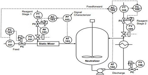
Figure 2.1
Question 3. (i) What is the difference between a process flow Diagram (PFD) and a Piping & Instrumentation Diagram (P&ID)?
(ii) What is the function of a pneumatic valve and how can it be classified?
Question 4. (i) State and explain two functions of pressure control valves.
(ii) What type of valve is shown on Figure 2.2. explain its operation function.
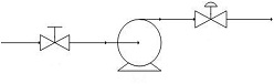
Figure 2.2
Question 5. Considering Figure 2.3, calculate the voltage between terminals 15 and 16 of TB27 when the measured flow rate is 106 GPM. Assume a loop power supply voltage of exactly 24volts and negligible wire resistance.
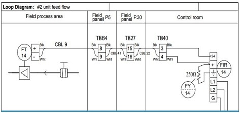
Figure 2.3: Loop Diagram of a Process Unit
Question 6. Suppose the steam tubes inside the heat exchanger shown on Figure 2.4 become coated with residue from the raw maple syrup, making it more difficult for heat to transfer from the steam to the syrup. This makes the heat exchanger less efficient, which will undoubtedly affect the process.
Describe in detail the effect this heat exchanger problem will have on the performance of the analytical control system.
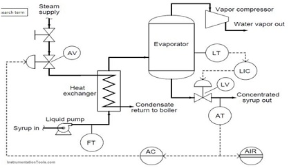
Figure 2.4: Heat Exchanger Diagram of a Process Unit