Reference no: EM133702651
Question 1: Match the functional description of the OSI layers on the left to the appropriate name of the layer on the right.
| defines procedures for accessing the media |
Application |
|
|
| standardizes the data formats between systems. |
Presentation |
|
|
| routes packets according to unique network address |
Session |
|
|
| cabling, voltages, bits, and data rates |
Transport |
|
|
| manages users sessions and dialogues |
Network |
|
|
| defines interfaces between application software |
Data Link |
|
|
| end-to-end message delivery over the network |
Physical |
Question 2: For this question, assume the following extract from a router's routing table.
Router# show ip route
<some Code output omitted>
172.30.0.0/16 is variably subnetted, 8 subnets, 4 masks
R 172.30.1.0/24 [120/1] via 172.30.2.1, 00:00:10, Serial0/0/0
C 172.30.2.0/30 is directly connected, Serial0/0/0
L 172.30.2.2/32 is directly connected, Serial0/0/0
C 172.30.3.0/30 is directly connected, Serial0/0/1
L 172.30.3.1/32 is directly connected, Serial0/0/1
R 172.30.6.0/24 [120/1] via 172.30.2.1, 00:00:10, Serial0/0/0
192.168.2.0/24 is variably subnetted, 2 subnets, 2 masks
C 192.168.2.0/24 is directly connected, Loopback0
L 192.168.2.1/32 is directly connected, Loopback0
192.168.5.0/24 is variably subnetted, 2 subnets, 2 masks
C 192.168.5.0/30 is directly connected, GigabitEthernet0/0
L 192.168.5.1/32 is directly connected, GigabitEthernet0/0
S 210.84.0.0/14 [1/0] via 192.168.5.2
a) Out which interface does the router send packets destined for 172.30.1.8?
b) Which dynamic routing protocol(s) are being used?
c) When routing a packet, how is the following entry used?
d) 172.30.0.0/16 is variably subnetted, 8 subnets,
e) What are the IP address and subnet mask of the interface Serial 0/0/1?
f) Describe how the router deals with a packet destined for 210.84.55.12?
g) What are the useable addresses in the network attached to interface Serial 0/0/0? How are they being used?
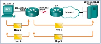
Question 3: In the below network topology diagram, PC1 is communicating with a Web Server through a NAT-enabled router R1.
The IP address of PC1 is 192.168.51.5, the IP address of the Web Server is 209.165.201.11, and the IP address of R1 interface S0/0/0 is 64.100.10.2.

On R1, the following configuration has been found:
interface s0/0/0
ip nat outside
interface fa0/0
ip nat inside
ip nat inside source list 1 interface serial 0/0/0 overload
access-list 1 permit 192.168.51.0 0.0.0.255
Follow this communication one hop at a time (as shown in the figure), and use the information provided in the diagram as well as in the below table to determine how the source IP address (SA), destination IP address (DA), and port numbers change along the way.
Complete the table with the appropriate SA, DA, source port (Src. Port) and destination port (Dest. Port) addressing to the corresponding fields for each hop of the communication.
|
Hops
|
Source Address
|
Destination Address
|
Src. Port
|
Dest. Port
|
|
Hop 1: PC1 to R1
|
192.168.51.5
|
209.165.201.11
|
1149
|
80
|
|
Hop 2: R1 to Web Server
|
|
|
1333
|
|
|
Hop 3: Web Server to R1
|
|
|
|
|
|
Hop 4: R1 to PC1
|
|
192.168.51.5
|
|
|