Reference no: EM132689616 , Length: word count:3000
Question 1
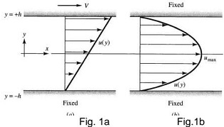
The analytical solution of laminar flow through infinitely long 'parallel plates' (also called plain channel) can be derived from the full 3-D Navier-Stokes (NS) governing equations via simplification with given boundary conditions. Fig. 1 a below shows an upper plate driven flow with the bottom plate fixed. Fig. 1 b shows a pressure driven flow with both upper and lower plates fixed. The channel height is 2h (h=10 mm) and the flowing fluid is water at a constant temperature of 25 °C. Ignore the effects of gravity.
(1.a) Using Cartesian coordinates, simplify the full 3-D unsteady compressible NS equations into 1-D (one dimensional) steady incompressible laminar flow equations. You should clearly explain and justify all steps and the reasons for the simplifications.
(1.b) Considering the boundary conditions in Fig. 1 a (fixed bottom plate, moving upper plate at constant velocity V), with zero pressure gradient along streamwise direction (dp/dx=0):
(1.b.i) Derive the analytical solution of the streamwise velocity profile u(y) and the general formula of the volumetric flow rate Q
(1.b.ii) For V= 0.1 m/s, calculate the flow Reynolds number (based on density, mean velocity, channel height, viscosity) and determine the value of the volumetric flow rate Q. Take the water properties (density, viscosity etc...) at 25 °C from the literature. For the volume flow rate calculations, you may assume a unit width of the plate.
(1.c) Considering the boundary conditions in Fig. 1.b (fixed bottom and fixed upper plate), water flow driven by a non-zero constant pressure gradient dp/dx (with dp/dx=-1 Pa/m):
(1 .c.i) Derive the analytical solution of the streamwise velocity profile u(y) and the general formula of the volumetric flow rate Q
(1.c.ii) Calculate the flow Reynolds number (based on density, mean velocity, channel height, viscosity) and determine the value of the volumetric flow rate Q. Take the water properties (density, viscosity etc...) at 25 °C from the literature. For the volume flow rate calculations, you may assume a unit width of the plate.
(1.d) We now consider a flow condition which is a combination of the above conditions: fixed bottom plate, moving upper plate at constant velocity V, a non-zero constant pressure gradient dp/dx along the streamwise direction.
(1 .d.i) Derive the analytical solution of the streamwise velocity profile u(y) and the general formula of the volumetric flow rate Q;
(1.d.ii) Calculate the flow Reynolds number (based on mean/bulk velocity) and determine the volumetric flow rate Q for the following parameters: V= 0.1m/s, dp/dx=-1 Pa/m.
(1.e) Plot the velocity profiles obtained in questions (1.b.i), (1.c.i) and (1.d.i) together with a sketch showing the flow domain and specific boundary conditions.
Compare the velocity profiles and discuss thoroughly the effects of moving wall, pressure gradient and both.
Question 2
Use the available meshing tools in ANSYS to generate mesh and perform CFD calculations for the three-dimensional air flow over NACA0012 airfoil at the following given conditions:
Angle of attack: 2 degrees
Free stream flow velocity: chose any value between 30 m/s - 50 m/s
Free stream flow temperature: 20 °C
Chord length: 1 m
The generated unstructured mesh should reflect the key physical flow features, e.g. viscous boundary layer, rapid changes in flow field, etc. Also discuss and comment on mesh quality. To create the 3D slice of the airfoil, extrude the 2D profile with 0.05 m depth.
For this question you need to undertake the followings:
(a) Calculate the air flow Reynolds number (based on chord length), and Mach number and determine the flow status (laminar or turbulent, compressible or incompressible), select and justify the appropriate turbulence model (if required);
(b) Choose the right boundary layer thickness calculation formula; and estimate its value to be used in meshing procedure and demonstrate that inflation layers properly reflect the physical viscous layer
(c) Generate and present the mesh and report the mesh quality and resolution.
(d) Run CFD calculations on the generated mesh and analyse your results for drag and lift coefficients, and pressure distribution over the airfoil.
In your report, you should include supporting formula, domain, mesh parameters, graphs (including near wall) and also discuss your findings/results.