Reference no: EM131054055
Q1.
a) In relation to Fourier analysis state the meaning and significance of
i) odd and even functions
ii) half-wave symmetry {i.e. f( t + π ) = -f (t)}.
Illustrate each answer with a suitable waveform sketch.
b) State by inspection (i.e. without performing any formal analysis) all you can about each of the periodic waveforms shown in FIGURE 1 in terms of their Fourier series when analysed about t = 0.
FIGURE 1
Q2. Preamble
Controlled rectification is a technique widely used for controlling the power delivered to a load from a single or poly-phase a.c. supply. In this technique the flow of current to the load is controlled by an ‘electronic switch' that is used to switch on the alternating waveform at some set phase angle in its cycle. Two examples of such ‘switches' used in controlled rectification are the thyristor and the triac. The thyristor is a unidirectional current device [passes current in just one direction like a diode] whilst the triac is bidirectional.
A simple and very common application of controlled rectifier is to be found in the ‘light dimmer', a circuit example of which is given in FIGURE 2 using a triac. The triac is a three-terminal device having two terminals like a conventional diode and a third terminal that is the control gate. The timing of a pulse applied to the gate determines at what point in the cycle (‘firing angle' α) the triac will turn on. In this simplified example the firing angle is controlled by the setting of the potentiometer RP.
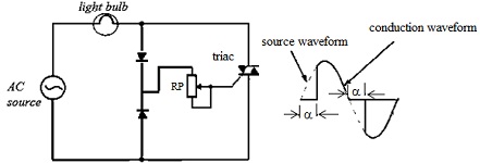
FIGURE2
Question 2
a) If the firing angle is set for α = Π/3 estimate the power dissipated in the bulb if it is rated at 100 W and the voltage source is 230 V @ 50 Hz.
b) An anomaly that can occur in controlled rectification is drift of the firing angle on one half cycle, so causing an asymmetrical waveform, as illustrated opposite. State the effect, if any, this would have on the harmonic content of the waveform.
c) Sketch the waveform defined below and explain how you would obtain its Fourier series:
f (ωt) = 0 for 0 ≤ ωt ≤ Π/2
f (ωt) = Vsin(ωt) for Π/2 ≤ ωt ≤ Π
f (ωt) = 0 for Π ≤ ωt ≤ 3Π/2
f (ωt) = Vsin(ωt) for 3Π/2 ≤ ωt ≤ 2Π
Develop the analysis as far as you are able.
Q3. Preamble
Techniques involving the electronic control of power to a load such as controlled rectification and variable frequency drives are widely used by industry. There can be, however, serious problems with these techniques because of the generation of harmonics and the consequential harmonic distortion. Harmonics, when fed back to the supply, can have adverse effects on other electrical equipment. It can increase the current in power lines resulting wasted power that causes higher temperatures in neutral conductors and distribution transformers. High order harmonics may cause excessive heating in the core of a.c. motors and can also interfere with communication systems. Increased temperatures can damage power systems and shorten the life of electronic equipment.
FIGURE 3 shows the oscilloscope trace of the supply current feeding a variable frequency drive (VFD).
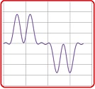
FIGURE 3
The supply current was sampled 1024 times over a very short time interval. The data so obtained is given in column B of the accompanying Excel worksheet1. This worksheet has been set up to give a graph showing the spectral components of the data.
Question 3
i) Obtain the Fourier Transform for the data using the Fourier Analysis tool of Excel. The transformed data should commence in cell D2.
ii) Identify the principal frequencies in the current waveform.
iii) Estimate the total harmonic distortion [THD] present in the current waveform using the formula:
THD(I ) = 1/I1√(Σn=2max(In)2 x 100%
where I1 is the r.m.s. value of the fundamental current, In the r.m.s value of the nth harmonic and n(max) is the number of the highest measurable or significant harmonic.
[Note the vertical axis of the spectrum graph is scaled in (current)2.]
iv) Attempt to synthesise the shape of the original waveform from its principal harmonics [e.g. sketch the waveforms of the harmonics on the same time axis and add them together].
Question 4 Sketch, on a set of common axes, waveforms to represent the transient response of circuits having transfer functions with the following parameters:
a) ς = 0.5, ωo = 1 × 10³ rad s-1
b) ς = 0.2, ωo = 2 × 10³ rad s-1
c) ς = 2, ωo = 1 × 10³ rad s-1
Q5 a) With the aid of a table of standard transforms, determine the Laplace Transform of:
a) 10 + 3t2 + sin4t
b) 4e-3t sin2t
b) With the aid of a table of standard transforms, determine the Inverse Laplace Transform of:
a) 5/s3 + 12/(s-4)
b) 3s + 9/(s+3)2 + 7
b) 3s + 9/(s + 3)2 + 7
Q6. Preamble
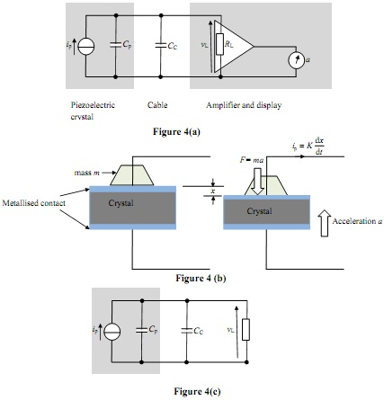
FIGURE 4(a) represents a system to measure acceleration (i.e. an accelerometer). It shows a piezoelectric crystal that is connected to an amplifier and display via a length of coaxial cable2.
A piezoelectric current is produced when the crystal is distorted by an applied force. In this application the force is produced by the reactive force of a mass when the accelerometer undergoes a change in velocity. The current ip is directly proportional to the rate of displacement, dx/dt, of one face of the crystal with respect to the other, as illustrated in FIGURE 4(b). Here ip = Kdx/dt, where K is a constant of proportionality. In Laplace form, ip (s) = KsΔx (s) .
In FIGURE 4(a) the piezoelectric crystal is modelled by a Norton current generator as a current ip in parallel with a capacitance Cp. The capacitance is due to the parallel-plate capacitor formed by the metallised contact plates placed on opposite faces of the crystal and the crystal itself forming the dielectric (see FIGURE 4(b)).
When a force F is applied across the face of the crystal, the current ip is generated. The interconnecting cable can be represented by a lumped capacitance CC. The input resistance of the amplifier, RL, acts as a load to the crystal. The output of the amplifier drives a display (a moving coil voltmeter that is calibrated in units of acceleration (ms-2)).
Question 6
a) Draw the Laplace form of the input portion of the circuit, as represented in FIGURE 4(c).
b) Derive an expression for the Laplace transfer function, T(s) = ΔvL(s)/Δip(s), of the circuit of FIGURE 4(c).
c) Express ΔvL as a function of time (i.e. the transient response of the voltage ΔvL ) when ip is subject to a step change.
d) Using the values given in TABLE A, estimate the time taken for the voltage vL to reach its steady state value if the current ip is subject to a step change of 2 nA.
| CP |
1400 pF |
| CC |
250 pF |
| RL |
5M |
Table 3