Reference no: EM133772835
Mechanism and Machine theory
Question 1:
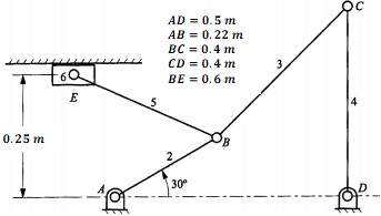
The crank AB shown in the figure below rotates at a speed of 120 rpm. Perform the following tasks:

1. Position analysis ← Start a new Matlab section here
a. Derive a closed-form position model (vector loop equation) for the linkage.
b. Use the model to animate the linkage on Matlab
2. Velocity analysis - mathematical-based method ← Start a new Matlab section here
a. Obtain the velocity model for the linkage in the form of a set of linear equations.
b. Graph the determinant of the main Jacobian against the crank angle.
c. Graph the velocities of all links against the crank angle
d. Graph the absolute velocity of the slider against the crank angle
3. Velocity analysis - graphical-based method
Graphically find the angular velocity of BC and BE, and the sliding velocity of E at the position shown in the figure. Use AutoCAD or similar software for your drawings.
4. Acceleration analysis ← Start a new Matlab section here
a. Obtain the acceleration model for the linkage
b. Graph the acceleration of all links against the crank angle c.
Question 2:
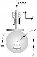
For the cam-follower mechanism shown, perform the following analysis:

- Write expressions for the follower displacement, velocity, and acceleration as functions of the cam angle, θ, and the cam dimensions. The angle θ can be measured with respect to +ve of the x- or y-axis.
- Sketch these relationships over a cam rotation of 360 degrees on one page.
- Find the stroke of the follower and the minimum face width it should have.
- Calculate the stiffness of the spring, which keeps the follower in contact with the cam at all, times.
- Find the power of the motor used to operate the mechanism
The cam radius is given as r = 80 mm and the pivot offset is a = 30 mm from the centre. The camshaft speed is 300 rpm in the counter-clockwise direction, and the follower mass is 2.5 kg. The spring deflection is 12 mm when the follower is at its lowest position. The follower operates against a constant force of 1200 N during its power stroke only. For the motor power calculations, neglect the spring force and the follower mass.
Question 3:
Design the following cam on Matlab. Motion particulars are as follows:
- The follower rises 25 mm (in a parabolic motion fashion) during a cam rotation of 90 degrees,
- The follower dwells during a cam rotation of 60 degrees,
- The follower rises an extra 20 mm (in a parabolic motion fashion) during a cam rotation of 90 degrees,
- The follower descends to its original position (in a simple harmonic motion - SHM) during a cam rotation of 100 degrees,
The camshaft speed is 150 rpm. For a follower mass of 6 kg, design a spring to ensure that the cam-follower contact is maintained at all times.
Obtain plots for the displacement, velocity, and acceleration of the follower against the cam angle of rotation. Plot the cam contour. In reality is it easy/possible to achieve the motion detailed above? Why/why not? What could be the limitation(s)?
What should be the best choice for the contact between this cam and the follower (i.e., flat face, roller, needle, slot,...). For the contact of your choice, modify the cam contour or slot to suit; make reasonable assumptions where necessary.
Question 4:
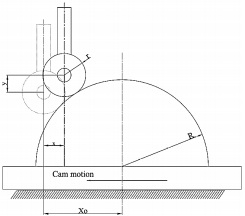
The attached figure indicates a reciprocating circular cam operating a translating roller follower, where both the cam radius R and the roller radius r are given. Find the maximum allowable stroke (2Xo) of the cam motion such that the pressure angle is kept in the range of ±30°.

Write symbolic expressions relating the follower displacement, y, and the pressure angle, φ, to the cam motion, x. If the follower rises against a resisting force N and a spring force Fs, neglect the frictional forces in the follower guides and write an expression to calculate the force Fc, as a function of N and Fs, required to drive the cam block in the horizontal plane. Take the coefficient of friction between the cam block and its guide in the horizontal plane as μ.