Reference no: EM13891620
1) Toy Processor Programming
In class we discussed 2 ways to write a program that calculates the sum of digits [0,... 9]=45. In a similar way, you are now asked to write 2 programs that load the Accumulator with 100 and then iteratively subtract these digits, so that in the end only 100-45=55 is left in the accumulator. The result should be finally stored in memory location 255. (Note: You are not allowed to first add the digits as we did in class and then subtract from 100.)
2) FSM Design
Design an FSM that recognizes an input sequence that has at least three 1's. More specifically, the FSM has one input, X, and one output, Y. Every clock cycle, a new symbol comes in through the input X. If at least 3 symbols of value "1" have been provided, then the output becomes 1 and remains 1 from then on.
(a) Define the necessary number of states and what each state represents. (Hint: You should be able to do this with 4 states)
(b) Show the state diagram of the FSM with all necessary transitions. Similar to the vending machine that we did in class, use the (condition)/(output) notation on the transition arrows to indicate the output value for each transition.
(c) Encode your 4 states and fill in the following Next State/Output Table
S0: Q1Q0= S1: Q1Q0= S2: Q1Q0= S3: Q1Q0=
| Current State |
Next State / Output |
| Q1 |
Q0 |
X = 0 |
X = 1 |
|
|
/ |
/ |
|
|
/ |
/ |
|
|
/ |
/ |
|
|
/ |
/ |
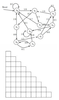
3) FSM Minimization
The following state diagram defines an FSM with notation x/y denoting an x input and a y output.
a) Use the Implication Table method to minimize the number of states of this FSM and list the equivalence classes of states. An empty table of appropriate size is provided for your convenience in the next page.
b) Draw the equivalent reduced state diagram containing the minimal number of states.
4) Memory Addressing Modes
The following are the contents of a Memory Array, Register File, and the specified register that is used to compute the effective address in certain addressing modes.
| Memory Array |
|
| 10 |
0 |
| 20 |
1 |
| 40 |
2 |
| 20 |
3 |
| 60 |
4 |
| 30 |
5 |
| 70 |
6 |
| 80 |
7 |
| 70 |
8 |
| 30 |
9 |
| 50 |
10 |
| 60 |
11 |
| 40 |
12 |
| 80 |
13 |
| 50 |
14 |
| 10 |
15 |
|
| Register File |
|
| 3 |
0 |
| 8 |
1 |
| 2 |
2 |
| 60 |
3 |
|
|
Identify the addressing mode(s) used for the following instruction/result pairs: (The addressing modes we discussed in the class are: Implied, Immediate, Direct, Indirect, and Relative. For some of them you need to specify whether they are Memory or Register based).
1) Load 3 → 60
2) Load 1,4 → 40
3) Load 6 → 60
4) Load 5 → 30
5) Load 0 → 50
----
Please solve any two questions with each and every necessary steps. Make sure to provide all sub-parts for choosing questions