Reference no: EM133044918
D21AR Advanced Design Of Reinforced Concrete Structures - Heriot-Watt University
Question 1
(a) Sketch the physical models adopted by Eurocode 2 and by the Compressive Force Path method for describing the behaviour of the structural members shown in Figures 1 to 4 when approaching the ultimate limit state (note that the designdetails of the specimens are only provided indicatively, no calculations arerequired):
Case 1: A short simply supported RC beam subjected to a point load at its midspan (see Figure 1). Assume a concrete cover of 30mm
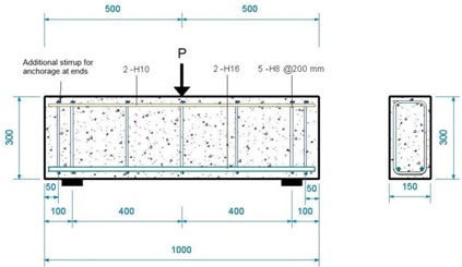
Figure 1: Short simply supported RC beam subjected to 3-point bending (all distances measured in mm).
Case 2: A slender simply supported RC beam subjected to a point load at its mid-span (see Figure 2). Assume a concrete cover of 30mm
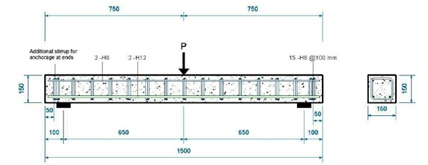
Figure 2: Slender simply supported RC beam subjected to 3-point bending (all distances measured in mm).
Case 3: An RC wall fixed at its bottom end and subjected to a horizontal load on its top as shown in Figure 3 (ignore the beams located on the top and bottom of the wall; these were used to fix the wall at its base and to apply the load on top).
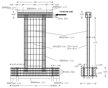
Figure 3: RC wall fixed at its bottom end and subjected to a horizontal load on top (all distances are measured in m).
Case 4: An RC beam supported as shown in Figure 4 and subjected to two equal concentrated loads (P1 = P2).
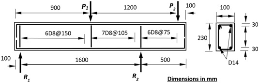
Figure 4: RC beam subjected to two concentrated loads
(b) For the case of the simply supported beam presented in Figure 2 and in accordance with the truss analogy, describe how the bending moments and the shear forces are transferred through its span to the supports. Based on the truss analogy model, what are the likely causes of brittle failure?
(c) Considering the crack patterns shown in Figures 5a and 5b that develop on the surface of the specimens shown in Figures 1 and 3 respectively, what are the modes of failure likely to be exhibited at peak load? (no calculations arerequired).
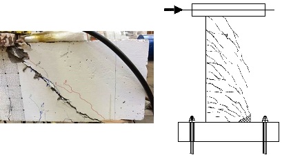
(a) (b)
Figure 5: Crack patterns exhibited by the specimen shown (a) in Figure 1 (Case 1) and (b) in Figure 3 (Case 3) as they approach the ultimate limit state.
(d) In accordance with the Compressive Force Path Method, describe the brittle mode of failure that the beam in Figure 1 is likely to have been exhibited if it had no shear links along its span. Consider the shear span to depth ratio when answering the question.
(e) What is the point of contra-flexure along the span of an RC beam/column element? Describe the brittle mode of failure that may occur at that location if not appropriately designed. At which point along the span of the beam specimen presented in Figure 2 will the point of contra-flexure occur? What would you do to ensure that brittle failure does not occur at that point?
(f) Describe the incompatibilities identified by the Compressive Force Path Method between a truss model (used to describe the behaviour of an RC member) and concrete material behavior.
(g) What are the causes of Type II failure in accordance to the Compressive Force Path Method for the case of a simply supported RC beam subjected to a 4-point bending test? Describe how the cracks are expected to extend along the span of the beam until failure occurs.
Question 2
Design the simply supported RC beam shown in Figure 4, first in accordance with the CFP method and then in accordance with Eurocode 2 for the following two cases, so as to exhibit ductile behaviour.
Case 1: Assume that the beam has a rectangular cross-section with an effective depth no less than 700mm.
Case 2: Assume that the beam has a rectangular cross-section with a effective depth less than 400mm.
The clear span (distance between the supports) of the beam is L = 7000 mm
The uniaxial cylinder compressive strength of concrete is fc = 40 MPa and the corresponding tensile strength is ft = 3.5 MPa. The yield strength for the longitudinal reinforcement is fy = 500 MPa whereas for the transvers reinforcement you can choose between fy = 500 MPa or fy = 250 MPa (all safety factors can be assumed equal to 1).
The beam is subjected to two concentrated loads (P = 450kN) applied symmetrically about the mid-span, at a distance of 1400mm from each support.
What are the differences in the arrangement of the reinforcement specified by both design methods employed? Depending on the dimensions selected, sketch the physical models adopted by Eurocode 2 and by the Compressive Force Path method for describing the behaviour of your beam when approaching the ultimate limit state.
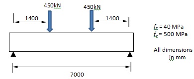
Figure 4: Simply supported beam subjected to a four-point bending test
Question 3
Provide a summary of the conclusions you have drawn from your coursework (exercises) that you have done during the semester when comparing the solutions obtained using Eurocode 2 to those obtained using Compressive Force Path (CFP) method. How did they compare to the available test data? Consider each of the exercises you have solved over the semester separately and provide a summary of your results and conclusions for each problem considered.