Reference no: EM133100817
ITECH1100 Understanding the Digital Revolution
Lab - Logic and Binary
Overview
In this lab, you will solidify your understanding of binary numbers and logic circuit diagrams
Task Details
Task one - Truth tables and logic circuit diagrams
Truth tables are a way of representing the behaviour of a system for all inputs. Logic circuit diagrams are a standard way of representing combinations of logical operators in diagram form. In this task, you will be converting truth tables to and from logic circuit diagrams.
Task 1.a - Interpret logic circuit diagrams
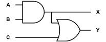
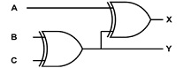
Complete the truth tables for each of the following logic diagrams
Task 1.b
Complete the logic circuit diagrams for each of the following truth tables.
Truth table 1 : what is the relationship between X and A? What is the relationship between Y and B?
|
A
|
B
|
X
|
Y
|
|
0
|
0
|
1
|
1
|
|
0
|
1
|
1
|
0
|
|
1
|
0
|
0
|
1
|
|
1
|
1
|
0
|
0
|
Truth table 2
|
A
|
B
|
X
|
Y
|
|
0
|
0
|
1
|
0
|
|
0
|
1
|
1
|
0
|
|
1
|
0
|
0
|
0
|
|
1
|
1
|
0
|
1
|
Truth table 3 (Optional, tricky)
|
A
|
B
|
X
|
Y
|
Z
|
|
0
|
0
|
1
|
0
|
1
|
|
0
|
1
|
0
|
1
|
1
|
|
1
|
0
|
0
|
0
|
0
|
|
1
|
1
|
1
|
0
|
1
|
You can use a diagramming tool such as Visio to create your logic circuit diagrams, but sketching on paper is fine too! The above logic diagrams were created using draw.io
How can you verify that your design works?
Task 1.c
Create a truth table and logic circuit diagram for each the following situations
• If you see a clown at the circus, it's ok to stay and watch them. In any other situation, you should run away from clowns. Create a truth table and logic circuit diagram with two inputs (do I see a clown, am I at the circus) and one output (should I run away)
Tip: make sure your diagram does not make you run away if you are at the circus but do not see a clown! The simplest solution uses one AND gate and one NOT gate.
• If Anna is hungry, and it is lunchtime, and she has brought her lunch with her, she will eat lunch. Create a truth table and logic circuit diagram with three inputs (hungry, lunchtime, have food) and one output (should I eat lunch)
• A hotel room has two lamps, each with an on/off switch. However, there is also a single main switch which enables the lamps to function. If the main switch is off, the two lamps won't work even if their individual switches are on. If the main switch is on, the individual switches work as normal. Your truth table and diagram should have three inputs (on/off for each switch) and two outputs (one for each lamp)
• Optional, extra tricky! A lecturer likes chocolate ice-cream on its own or with chocolate sprinkles, but never in a cone. They also like vanilla ice-cream but only if it is in a cone and has chocolate sprinkles on it. Your truth table and diagram should have three inputs (is it chocolate flavour, are there sprinkles, in a cone) and one output (would the lecturer like it)
Task two - Binary and representing integers
Task 2.a
How many unique values can be stored in:
• 2 bits
• 1 byte
• 6 bytes
• 128 bits
Task 2.b
Convert the following decimal numbers to binary (manually!) using either the divide-by-two method from the lecture, or any other way that makes sense to you. The other main approach is the subtraction method
• 3 • 7
• 8
• 12 • 77
Verify your conversions using the calculator tool in Moodle.
Task 2.c
Convert the following binary numbers to decimal (manually!). Refer to the powers of two in the table as required.
|
2288
|
2277
|
2266
|
2255
|
2244
|
2233
|
2222
|
2211
|
2200
|
|
|
|
|
|
|
|
|
|
• 10
• 111
• 1101
• 10110
• 100110
• 1000100
Verify your conversions using the calculator tool in Moodle.
Extended research: What is hexadecimal and why would we use it in IT?
Task three - Excel as a logic calculator
Microsoft Excel is one of the most fundamental tools used in IT and Business.
Often entire business processes are driven by Excel. This week we will explore using Excel to implement the divide by two method of binary conversion.
Task 3.a - Logic functions in Excel
Launch Microsoft Excel and create a blank workbook
You may also use an open-source equivalent, such as LibreOfficeCalc, however you will have to adapt these instructions
If you have never used Excel before, take a moment to familiarize yourself with the interface.
Coverage of some fundamentals is available in an extra resource in the document Excel Fundamentals on Moodle.
Logic values and functions
Excel includes logical values - TRUE and FALSE - and logical functions, such as AND(), OR(), XOR() and NOT().
Try switching some values from TRUE and FALSE to 0 and 1 in the spreadsheet. Does it make a difference?
Task 3.b - Implement decimal to binary with Excel
The divide-by-two method of converting decimal numbers to binary in Excel requires repeated division by two, and taking the remainder.
Excel has built-in support for both of these, however the standard division operator, / (forward slash), can give a result with a fractional component.
To perform division and discard the remainder, you can use an Excel function called INT()
We also need the remainder of the division, the Excel function MOD() can do this ?Look up the help for INT and MOD functions in the Excel help system.
With these two tools, implement the divide-by-two method of decimal-binary conversion in Excel, so that it supports (at least) 8-bit numbers.
Hint: you will need to choose an input cell, and then for each step of the algorithm you need a cell for the result of the division and the remainder. The divided result is used as the input for the next step of the algorithm.
Extended task - Full adder
Task 4.a
Construct a truth table and logic circuit diagram for an adder which takes three inputs, and returns the sum as a two-bit binary value.
That is, your system should count how many inputs are on.
Task 4.b
Using the half-adder from the lecture slides for the lowest bits, and your new three-input adder, create a circuit which can add two-bit numbers. Hint: the carry output from the half-adder is connected as one of the inputs of the three-input adder.
How would you extend this to higher numbers of bits?