Reference no: EM13342734
Design of a 4-bit cascaded adder
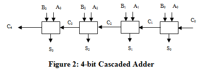
In this task, you are to design an N-bit binary adder by cascading N Full Adders in series. The idea is to have the adder mimic the way we do addition with pencil and paper. When we do addition with paper and pencil, we start from the LSB (least-significant bit) column, add each pair of bits in sequence and add the carry from one column of bits to the sum of the column to its left. In other words, we form the ith sum Si by adding the pair of bits in the ith column and the carry-out from (i-1)st column. We can therefore get the sum at each column by using a Full Adder circuit. The sum of two N-bit numbers can be obtained by cascading a series of N Full Adders. Figure 2 shows a block diagram of a 4-bit adder

The multi-bit adder described is usually called a cascaded adder or a ripple-carry adder (because the carry ripples from one column to the next). The method described above of cascading single bit building blocks (called bit slices) to form multi-bit operations is very common is digital design. Its benefits are obvious: it allows us to build a complex circuit that realizes a complex function by replicating the same simple circuit N times, cutting down on design and implementation costs.
1) To what value should the LSB carry, C0, be set?
2) Design a 4-bit cascaded adder.
3) Create a new device symbol for the Full Adder and save it.
4) Use the Full Adder component to build the 4-bit cascaded adder. Simulate you circuit in Logic Works and test it.
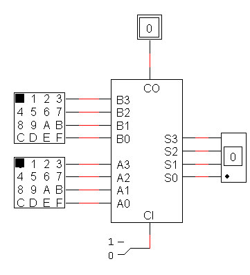
5) Create a new device symbol for the 4-bit cascaded adder. Demo its operation using hex-keyboards and a hex display device (see diagram of figure 3 below).
6) Turn-in a printout of your design and of the test data used to test the circuit. Note: you need to have the test data ready for the demo.

Figure 3