Create a beam finite element model of the ladder

Assignment Help Mechanical Engineering
Reference no: EM132272727

COMPUTATIONAL MECHANICS

Assignment

The attached drawing shows details of one-half of a step ladder. This ladder consists of two 85 mm x 20 mm x 2 mm (thick) aluminium channel-section rails with 5 steps equally spaced at a vertical height of 300 mm. A 2 mm thick aluminium cap at the top of the ladder - see Section B in the drawing for details - provides the top step for this ladder. The main steps here are assumed to be constructed in two halves and pressed together to form the complete step. Each of these sections is manufactured from 1mm thick aluminium and, when pressed together to form the step, parts that touch together - the centre section and two end parts of the step (see drawing for details) - effectively form a 2mm thick section. The steps are connected to the rails using the two oval-shaped part of the step protruding through and held to the rails; see figure 1. For this assignment assume the aluminium has a yield strength to 300MPa. Note even though the ladder in this assignment is based on the geometry of a commercially available step ladder, several simplifications have been made so much so that the results from this model cannot be used to infer the mechanical strength of similar shaped commercially available ladders.

2405_Ladder step connection to rails.jpg

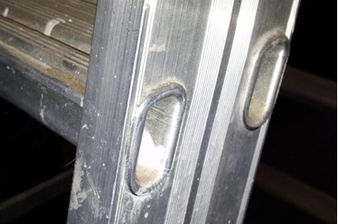
Figure 1. Ladder step connection to rails

In this assignment you are required to:

1. Create a beam finite element model of the ladder shown in the drawing. This will require you to build the step cross-section in Strand7 using the details supplied in the drawing. I suggest you save this plate cross-section of the step as a separate model as it will be useful in part 2 of the assignment.

2. Create a detailed plate finite element model of the step ladder. I suggest you start with the plate cross-section model of the step and use this geometry to define beams on the centreline of all parts of the step allowing you to create the plate model by extrusion. The difficult part in building this model is creating the plate finite element mesh at the intersection between the step and the rail. I suggest you build this mesh before extruding the beams on the cross-section to create a plate mesh of the step. I will discuss this part of the assignment in class.

3. For both models, create boundary conditions simulating the ladder leaning up against a wall with the rail making an angle of 70° to the horizontal (as per the drawing). Here prevent nodes "on the ground" from moving vertically and horizontally outwards and on the wall from moving horizontally. Note you need to prevent a sufficient number of nodes in the model from moving horizontally perpendicular to the outwards direction to prevent rigid body motion. Apply a vertical load equivalent to 120kg on the middle step simulating a person standing on the step. I will leave the method of applying this load in the beam and plate models up to you but you need to document your method in the report. For both models, determine the deflection and stress within the step- ladder under load. Compare predictions from the models and comment. You may want to look at predicted deflections and stresses, location of high stress points, deflected shape under loading, factor of safety determined from both models and predicted weight of both models (use the same grade of aluminium alloy in each model).

Report
Submit a report documenting all requested information outline above.

Reference no: EM132272727

Questions Cloud

What would be its arrival time in frankfort : What would be its arrival time in Frankfort? Use your resources to find the time difference between the two cities.
Financial condition of organization at any given moment : It is important for management officials to know the financial condition of the organization at any given moment.
Which types of business challenges : Which types of business challenges did Ming most likely describe to the shop owner?
Create data flow diagram : Create a data flow diagram to illustrate how systems will interact with the customer and how the data are passed through the system(s),
Create a beam finite element model of the ladder : MECH4400 - Computational Mechanics - University of Newcastle - Create a beam finite element model of the ladder shown in the drawing
Unity and the gnome desktop environments : Question 1: What are some of the differences between Unity and the GNOME desktop environments?
Discuss at least two ethical occurrence in government : Identify and discuss at least two "ethical occurrence" in government. Thoroughly discuss why you feel the occurrence is ethically questionable or admirable.
Agile development methodology : What are the major problems (or side-effects) while using Agile Development Methodology (for example Scrum and XP)?
Workplace in the near future or in the long term : Do you think that you can apply any of the systems analysis and design concepts that we learned (FURPS+, use cases, class diagram, activity diagram

Reviews

len2272727

4/2/2019 1:30:40 AM

Submit a report documenting all requested information outline above. I suggest adding suitable pictures of your model from Strand7 into your report. Before creating the jpg picture, ensure the screen background colour is white. Select the gear looking icon select View options select the white colour and select solid – see below Hand-in a hardcopy of your report and submit all your strand7 models (files with .st7 extension) via a zipped file to blackboard for assessment. Issued: Friday 22nd Due: 5pm Monday 15th

Write a Review

Mechanical Engineering Questions & Answers

  Package design

Package Design Brief: Assume you are the packaging engineer for a large consumer products company. In this company, the Packaging Design Briefs are initiated by the marketing group and forwarded to the Package Engineering group.

  Mechanical engineering questions

Define dynamic viscosity, Determine the centroid, Pressure due to the height of liquid, Advantage of changing the liquid, Calculate the total moment about the hinge of the seal gate.

  Automatic control

DOF system and Find the differential equation describing the system

  Write a paper on boyle''s law

Write a paper on Boyle's law and describe Compression and Combustion stroke . Also explain Charles's law and illustrate SI engine and CI engine.

  Verify the law for parallelogram of forces

To Verify the law for parallelogram of forces, law for triangle of forces and law of polygon of forces. These laws are very useful to calculate unknown forces in very short time.

  Discharge pressure of the compressor

What is the discharge revised discharge pressure of the compressor.

  The Case for Global Accounting Standards

The role of IFRS in both developing and developed capital markets.

  Wind turbine

Wind turbines are becoming more and more common as a method of energy production, wind turbines by their very nature are dynamic and are subject to and create their own internal and external kinematics and kinetics.

  Advanced design methodologies

8 x product engineering and design review (week 2 – 12), ~3 pages per item which must contain a brief description of the product then delve into concepts such as materials selection, manufacturing methods, life cycle analysis, recyclability and overa..

  Design of absorption column and the cooler

Design of absorption column and the cooler. Process design of other units should be completed along with pipe sizes.

  Determine the maximum total bending moment

Determine maximum total bending moment (static plus dynamic) of the beam under steady-state conditions.

  Force of the water on the gate

Determine the magnitude of the horizontal and vertical components of the force of the water on the gate.

Free Assignment Quote

Assured A++ Grade

Get guaranteed satisfaction & time on delivery in every assignment order you paid with us! We ensure premium quality solution document along with free turntin report!

All rights reserved! Copyrights ©2019-2020 ExpertsMind IT Educational Pvt Ltd