Reference no: EM132154971
Networking and Routing Basics Case Study Assignment -
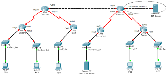
Network Topology Diagram -
Objectives -
- Create an Addressing Scheme.
- Basic Device Configuration.
- Configure RIP.
- Configure and redistribute Static Routes.
- Configure ACL.
- Verify connectivity.
- Documentation.
Task 1: Create an Addressing Scheme.
Assign the first available IP address in a subnet to the Host PC's or Server.
Assign the last available IP address in a subnet to the Router interfaces.
Use the 209.165.180.0/24 address range to create an addressing scheme for the link connecting the two campus routers.
Step 1: Use the 172.16.0.0/16 address range to create an addressing scheme to accommodate all other devices connected to the Campus1 router. Document the information in Table1 and Table2.
Table1
|
Device
|
Interface
|
Number of Hosts
|
Network Address
|
Subnet Mask
|
Broadcast Address
|
|
Campus1
|
S0/0/0
|
2
|
|
|
|
|
S0/0/1
|
2
|
|
|
|
|
Fa0/0
|
2
|
|
|
|
|
Student
|
S0/0/0
|
2
|
|
|
|
|
Fa0/0
|
31
|
|
|
|
|
Fa0/1
|
500
|
|
|
|
|
Staff
|
S0/0/1
|
2
|
|
|
|
|
Fa0/0
|
260
|
|
|
|
Table2
|
Device
|
Interface
|
IP Address
|
Subnet Mask
|
Default Gateway
|
|
Campus1
|
S0/0/0
|
|
|
|
|
S0/0/1
|
|
|
|
|
Fa0/0
|
|
|
|
|
Student
|
S0/0/0
|
|
|
|
|
Fa0/0
|
|
|
|
|
Fa0/1
|
|
|
|
|
Staff
|
S0/0/1
|
|
|
|
|
Fa0/0
|
|
|
|
|
PC0
|
FastEthernet
|
|
|
|
|
PC1
|
FastEthernet
|
|
|
|
|
PC3
|
FastEthernet
|
|
|
|
Step 2: Use the 192.132.14.0/24 address to create an addressing scheme to accommodate all other devices connected to the Campus2 router. Document the information in Table3 and Table4.
Table3
|
Device
|
Interface
|
Number of Hosts
|
Network Address
|
Subnet Mask
|
Broadcast Address
|
|
Campus2
|
S0/0/0
|
2
|
|
|
|
|
S0/0/1
|
2
|
|
|
|
|
Fa0/0
|
2
|
|
|
|
|
Admin
|
S0/0/0
|
2
|
|
|
|
|
Fa0/0
|
12
|
|
|
|
|
Fa0/1
|
16
|
|
|
|
|
Resources
|
S0/0/1
|
2
|
|
|
|
|
Fa0/1
|
24
|
|
|
|
Table4
|
Device
|
Interface
|
IP Address
|
Subnet Mask
|
Default Gateway
|
|
Campus2
|
S0/0/0
|
|
|
|
|
S0/0/1
|
|
|
|
|
Fa0/0
|
|
|
|
|
Lo0
|
|
|
|
|
Admin
|
S0/0/0
|
|
|
|
|
Fa0/0
|
|
|
|
|
Fa0/1
|
|
|
|
|
Resources
|
S0/0/1
|
|
|
|
|
Fa0/1
|
|
|
|
|
Resources Server
|
FastEthernet
|
|
|
|
|
PCS
|
FastEthernet
|
|
|
|
|
PC6
|
FastEthernet
|
|
|
|
Step 3: Cable and configure the network based on the given topology.
Task 2: Basic Device Configuration.
Step 1: Configure all the devices with the hostnames as given in the network topology diagram.
Step 2: Configure the privileged exec password. Use "cisco" as the secret password.
Step 3: Secure console connection by using "class" as the password.
Step 4: Secure the virtual line connection by using "cisco" as the password.
Step 5: Configure a message-of-the-day banner, "Unauthorized users will be prosecuted".
Step 6: Configure all devices with the correct IP address, subnet mask and default gateway
Task 3: Configure RIP
Step 1: Configure RIPv2 on the Student, Staff, Resources and Admin routers. Advertise all networks.
Step 2: On the Campus1 router, configure RIPv2 on all the links except the link connecting the Campus2 router. (Do not include the network connecting Campus1 and Campus2)
Step3: On the Campus2 router, configure RIPv2 on all the links except the link connecting the Campus1 router. (Do not include the network connecting Campus1 and Campus2)
Step 4: Disable Automatic-Summarization.
Step 5: Stop routing updates from entering interfaces where these advertisements are not needed.
Step 6: Verify RIPv2 configuration and operation.
Task 4: Configure Static Routes
Step 1: Configure a static route on the Campus1 router such that all connected devices can reach the devices on the Campus2 router. Propagate the static route to all connected devices on the Campus1 router.
Step 2: Configure a static route on the Campus2 router such that all connected devices can reach the devices on the Campus1 router. Propagate the static route to all connected devices on the Campus2 router.
Task 5: Configure ACL
Step 1: Configure an ACL such that devices in the Staff and Student networks can communicate with the Resources Server only.
Step 2: Configure an ACL such that only the devices in the IT and HR networks can communicate with the ISP Server.
Task 6: Verify Connectivity
Step 1: Ping the ISP Server from all the end devices.
Step 2: Ping the Resources Server from all the end devices.
Step 3: If you are unsuccessful, troubleshoot the configurations using the appropriate commands.
Task 7: Documentation
Copy the running configuration of all the routers to separate notepad files. Upload the addressing scheme and the configuration files to StudentWeb.