Compute the closed loop transfer function of the system

Assignment Help MATLAB Programming
Reference no: EM131950640

1. Calculate K value for the system. Write a MATLAB code to compute the closed loop transfer function of the system. Plot the Bode plot and compute and Compute using MATLAB the setting time and percentage overshoot of the system for this value, compute again for another. Plot the response to unit step response.

2. Obtain the controller gain for each. Using MATLAB sketch the root locus for the given controller. Do the same for other two controllers. Plot the unit step response of the controllers. Compare the three by finding the steady state error and transient response.

3. Using SIMULINK determine the unit step response for the given system. Compute analytically the digital algorithm for the given system. Draw the block diagram representation for the digital system. Now using SIMULINK compute the response for the digital system. Compare the two plots.

4. Write a report on any implementation of controller using microcontrollers for real life application. Report must have details on the application of the controller, implementation of the controller, interfaces used and why micro controllers are used to implement the controller.

PART 1:

1. Consider the problem of controlling an inverted pendulum on a moving base, as shown in Figure 1. The transfer function of the system is

G(s) = ((-1)⁄((MbL)))/(s2-(Mb + Ms)g/(MbL))

Where:

Mb - mass of the moving base
Ms - mass of the pendulum
L - length of the rod from pendulum to base

The design objective is to balance the pendulum (i.e., θ(t)≈0 in the presence of disturbance inputs. A block diagram representation of the system is depicted in Figure 2. Let Ms = 10 kg,Mb =100 kg,L = 1 m,g = 9.81 m/s2. The design specifications, based on a unit step disturbance, are as follows:

Settling time (with a 2% criterion) less than 10 seconds,
Percent overshoot less than 40%, and
Steady-state tracking error less than 0.1° in the presence of the disturbance.

1802_figure.jpg

Figure 1

2294_figure1.jpg

Figure 2

Develop a set of interactive m-file scripts to aid in the control system design.

a. The first script should accomplish at least the following:
Compute the closed-loop transfer function from the disturbance to the output with K as an adjustable parameter.
Draw the Bode plot of the closed-loop system.
Automatically compute and output the Maximum Peak,? M?_pω and resonant frequency, ω_r. As an intermediate step, use M_pω and ω_r and estimate damping ratio ζ and natural frequencyω_n.

b. The second script should at least estimate the settling time and percent overshoot using ζ andω_n as input variables. If the performance specification are not satisfied, change K and iterate on the design using the first two scripts. After completion of the first two steps, the final step is to test the design by simulation.

c. The functions of the third script are as follows:
Plot the response θ(t), to a unit step disturbance with K as an adjustable parameter, and
Label the plot appropriately.

Utilizing the interactive scripts, design the controller to meet the specifications using frequency response Bode methods. To start the design process, use analytic methods to compute the minimum value of K to meet the steady-state tracking error specification. Use the minimum K as the first guess in the design iteration.

2:

Consider the feedback control system in Figure 3. We have three potential controllers for our system:
Gc(s) = K (proportional controller)
Gc(s) = K/s (integral controller)
Gc(s) = K(1+ 1/s) (proportional, integral (PI) controller)

1356_figure2.jpg

Figure 3

The design specifications are T_s≤10 seconds and P.O.≤ 10% for a unit step input.
For the proportional controller, develop an m-file to sketch the root locus for 0 < K < ∞, and determine the value of K so that the design specifications are satisfied.
Repeat part (a) for the integral controller.
Repeat part (a) for the PI controller.
Co-plot the unit step responses for the closed loop systems with each controller designed in parts (a)-(c).
Compare and contrast the three controllers obtained in parts (a)-(c), concentrating on the steady-state errors and transient performance.
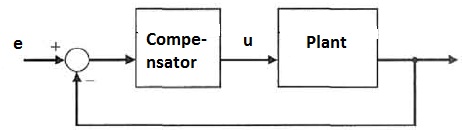
PART 2:
Consider the analogue control system shown in the figure. By root locus analysis, it is found that the closed loop natural frequency ωn=0.6 rad/sec. and the damping ratio is 0.5.

G(s) of compensator=2.2(s+0.1)/(s+0.01)
G(s)of plant=1/(s(s+1)(s+4))

We wish to replace the analogue compensator by a digital one. Select a suitable sampling interval and obtain an equivalent digital control algorithm using bilinear mapping. Give the block diagram of digital control system. Using Simulink/Control system tool box obtain the step response of the digital and analogue implementations. Compare the results.

Produce a detailed report on any application of microcontrollers in controller designs for real life application. Write about the kind of interfaces used for input and output data and also why microcontrollers where used for controller designs. (1200 words).

Brief
1. Calculate K value for the system. Write a MATLAB code to compute the closed loop transfer function of the system. Plot the Bode plot and compute M_pω andω_r.Compute using MATLAB the setting time and percentage overshoot of the system for this value, compute again for another. Plot the response to unit step response.

2. Obtain the controller gain for each. Using MATLAB sketch the root locus for the given controller. Do the same for other two controllers. Plot the unit step response of the controllers. Compare the three by finding the steady state error and transient response.

3. Using SIMULINK determine the unit step response for the given system. Compute analytically the digital algorithm for the given system. Draw the block diagram representation for the digital system. Now using SIMULINK compute the response for the digital system. Compare the two plots.

1547_figure3.jpg

4. Write a report on any implementation of controller using microcontrollers for real life application. Report must have details on the application of the controller, implementation of the controller, interfaces used and why micro controllers are used to implement the controller.

Reference no: EM131950640

Questions Cloud

Investigate how to measure brand performance : Branding involves creating a logo, name, or other recognizable images in the consumers mind to form a significant presence in the marketplace.
What is the holding period return on investment for year : One year ago you purchased a share of stock for $15.44. What is the Holding Period Return on this investment for the year?
Find the total cost of renting and driving the hybrid car : Find the total cost of renting and driving the hybrid car for the trip. The total cost will be?
Calculate the sml formula for portfolio of stocks : A hedge fund manager wishes to calculate the SML formula for his portfolio of stocks.
Compute the closed loop transfer function of the system : ENGD2050 Control and Instrumentation Engineering - Write a MATLAB code to compute the closed loop transfer function of the system. Plot the Bode plot
What data or property is threatened and how critical is it : What data or property is threatened and how critical is it? What is the impact on the business should the attack succeed? Minimal, serious, or critical?
Calculate rate of return : Calculate the rate of return under the scenario. You purchase a coupon bond with a coupon rate = 5.5% and a face value of $1,000 for $1,100.
Identify the marketing mix of this organisation : Consider the companies Barry Callebut, Cargill, Mondelez, and Hershey. With a focus on one of these companies identify the marketing mix of this organisation
Center line and control limits for an x control chart : Calculate the center line and control limits for an x control chart. (Round your answers to two decimal places.)

Reviews

len1950640

4/20/2018 5:02:12 AM

4. • Application of the controller (5 marks) • Implementation of the controller using microcontrollers (5 marks) • Reason on implementing the controller using microcontrollers (5 marks) Submission instructions The coursework should follow the standard report format consisting of a. Coursework Mark sheet b. Title Page c. Main Report d. References ? The report should be printed using: Font, Times New Roman; Font size, 12; Line spacing, 1-1/2 and left-right justification. ? A report which does not meet the style and format specification will not be accepted for marking. It will be returned to the student and a mark of 0% recorded. If in any doubt about whether the work meets the style and format specification, seek advice from the module leader. ? Include a Reference Page at the end of your assignment and reference within the text according to Harvard style of referencing. ? References (Harvard Referencing) must be provided whenever you use someone else’s opinions, videos, computers, other print or electronic sources and personal communications. ? There will be a penalty for late submissions. Refer to student handbook for late submission penalties.

len1950640

4/20/2018 5:02:02 AM

• Determine the K value for Proportional, Integral and PI controllers (1*3=3 marks) • MATLAB code for root locus of the Proportional controller and output (4 marks) • MATLAB code for root locus of the Integral controller and output (4 marks) • MATLAB code for root locus of the PI controller and output (4 marks) • Plot of the unit step response for each of the controllers (1*3=3 marks) • Compare the three controllers (3*2=6 marks) • Output demonstration(2*3=6 marks) 3. • SIMULINK model for the analogue control system (5 marks) • Unit step response of the analogue model (2 marks) • Equivalent digital algorithm design for the analogue compensator (5 marks) • Block diagram representation of digital model (5 marks) • SIMULINK model for the digital control system (5 marks) • Unit step response of the digital model (2 marks) • Output demonstration(3*2=6 marks)

len1950640

4/20/2018 5:01:55 AM

Working Arrangements Calculation of K value (2 marks) MATLAB code for closed loop transfer function and output (4 marks) Bode plot of the system (2 marks) Compute M_p? and?_r(4 marks) MATLAB code for the setting time and percentage overshoot and output. (4 marks) MATLAB code for response to disturbance and output (3 marks) Output demonstration(2*3=6 marks)

Write a Review

MATLAB Programming Questions & Answers

  Create a function that will determine the total resistance

Create a function that will determine the total resistance of a number of resistors that are connected in parallel. This function should accept a row vector for input,

  How much did he spend each day

A hungry college student goes to the cafeteria and buys lunch. The next day he spends twice as much. The third day he spends $1 less than he did the second day. At the end of 3 days he has spent $35. How much did he spend each day? Use MATLAB's s..

  It is now cooled so the volume becomes half the initial

a piston cylinder loaded so it gives constant pressure has 0.75 kg saturated vapor water at 200 kpa. it is now cooled

  Find the acceleration by taking the derivative again

We can find the acceleration by taking the derivative again.

  Matlab code to create the global stiffness matrix

Write a MATLAB code to create the global stiffness matrix for a problem with 6 unconstrained degrees of freedom for any linear elastic two dimensional trusses.

  One-dimensional steady-state heat flow

A one-dimensional steady-state heat flow, the mathematical formulation of problem - find out the temperature differences at each locations and calculate the temperatures at each locations

  Write a function called matrix summary

Write a function called matrixsummary that takes in one argument, a matrix or a vector, and returns four output values - the sum, mean, max and min of all the values in the matrix or vector.

  How much time passes from when the wheel was started from

a sharpening stone at rest is brought to 300 rpm over 2 mins. at that point a dull sword edge is placed against the

  Evaluate the function at a range of x values

Write a function file, that accepts values of x as inputs and outputs the value of y when the input is passed through the following function. Evaluate the function at a range of x values from 0 to 1 with 143 elements.

  Calculate the vertical stress increase

Calculate the vertical stress increase expected 2.0 m under the ground surface, under the centre of a rigid 2m by 2m footing resting on the soil surface if the total contact load the footing places on the soil is 80kN.

  Matlab command that will create a ten-element column vector

MatLab command that will create a ten-element column vector named

  Write a matlab function

Write a Matlab function [P,L,U] = ColumnCroutLU(A) to perform the column- wise Crout method given by equations (3) and (4), overwriting the matrix

Free Assignment Quote

Assured A++ Grade

Get guaranteed satisfaction & time on delivery in every assignment order you paid with us! We ensure premium quality solution document along with free turntin report!

All rights reserved! Copyrights ©2019-2020 ExpertsMind IT Educational Pvt Ltd