Reference no: EM133042479
BEAM PROBLEM
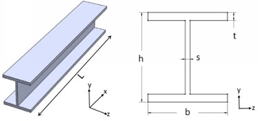
The configuration of the I-beam to be analyzed is shown in Figure 1. The beam is fixed at both the ends and carries a uniform pressure on the top log flange due to load from the slab.

Figure 1: Configuration of the beam to be analyzed: 3D (left), cross-section (right)
Consider I-beam of two different sections Normal and Deep with the dimensions given in Table 1. The difference between Normal and Deep sections can be seen in the last two columns of Table 1 showing the section dimensions compared to the length. The length (L) of the beam is 4000 mm. The dimensions of h, b, s and t are also in mm.

Use three modeling approaches:
Model the I-beam using three modeling approaches given below:
1) 3D solid element: all the dimensions of the beam are explicitly modeled.
2) Shell element - thicknesses of the flanges and Web are implicitly modeled
3) Beam element: except for length all the other dimensions are implicitly modeled as cross-section area for the beam.
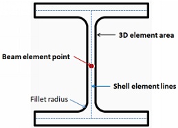
The cross-sections of the three models are given in Figure 2. Note that for the shell model the mid-surface of the beam is used. In other words the shell element lines go through the center of the Ranges and web. Actual thickness values of the flanges and web can then be assigned to the shell elements. The extrusion of the cross-section models along the beam length will provide the entire beam models. Note that in general there will be some fillet radius. You can ignore the fillet radius in the solid model, but do understand that if stress in fillet radius is important you will need to model all the fillet radii.

Figure 2: I-Section Models (red - beam element point, blue - shell element lines, black - 3D solid element area)
Finite element mesh requirements ;
For the 3D solid. element model the volume is discretized to meet the following criterion!
a) Use two element divisions across the flange and web thicknesses. This is the minimum required no adequately simulate the bending behavior of the flanges,
b) The aspect ratio (ratio of the largest to the smallest dimensions in any element) is not more than 5.
The resulting mesh patterns from 3D solid clement model along the flange, the web and the length directions should be retained for the shell element and he beam element models for consistent mesh density. This should result in same number (columns) of elements along the length of the beam for the solid, shell and beam meshes.
Element formulation types:
Use the following element formulation for the meshes;
a) Solid element: hexahedral (brick)
b) Shell element; quadrilateral shell
c) Beam element: Consider two cases (i) Euler-Bemoulli beam (no tansverse shear deformation), (ii)Timoshenko beam (with transverse shear defamation)
Material Properties (Steel):
Young's modulus (E): 200000 14Pa Poisson's ratio (v): 0.3
Load:
Pressure on the top flange due to slab: 0.1 MPa
Note: For beam element model pressure should be applied as a line load Newton per mm., equal to the pressure multiplied by the width of-the flange) on all the nodes.
USE SYMMETRY TO REDUCE MODEL SIZE!
Analysis:
(a) Mesh convergence
• Conduct mesh convergence study (use three mesh size) to ensure accuracy of your results or justify if mesh density is reasonable. Choose reasonable mesh size as a starting point or the study. To coarse of. aI mesh will not give accurate. results so don't use it. Refine this mesh further so that the results from two successive refinements are in close agreement. If the results of the last two mesh sizes are more or less same you can use the coarser mesh to reduce computation time.
Use the Deep beam section for the mesh convergence study and use the mesh size decided from the study for the other models and Norma] section.
• Use mid-span vertical displacement (uy) to check mesh convergence.
(b) Analysis results should include the following;
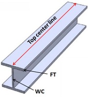
i. Compare the mid-span vertical displacement (uy) of the four models. Comment on the results. Note that for 3D solid and shell element model the top flange will bend relative to the web. For comparison use two points, the web center (WC) and the flange tip (FT) as shown in Figure 3 for displacement at the mid-span section. For quick summary present the results in a table.
ii. For comparison of stress, plot the variations of von Mises stress along the top center line. (see Figure 3) for the two configurations, Normal and Deep beam. Plot von Mises stress on the y-axis. and the corresponding nodal coordinate in direction on the x-axis. Keep the Normal and Deep beam plot separate. Comment on the results.
iii.Compare the computational time (cpu) taken for the four models. Comment on the results. Present the results in a table.
iv. Considering the results (displacement and stress model lug effort and.
computation time results of the different modeling approaches describe the pros and cons of each modeling approach (element type/formulation).

Figure 3: Flange tip (FT) and well center (WC) for measuring the displacement
WRITE-UP REQUIREMENT
The project write-up should be 5-10 pages from Introduction onwards and must contain the following items in sequential order:
I) Cover Page
2) Abstract (concise summary of the problem, approach to solve it and results)
3) Table of Content
4) List of Figures
3) List of Tables (if any)
6) Introduction (give background of the problem to be solved)
7) Main Body (divided into sub-sections as needed)
a) Conclusion (conclusion summarizing the problem, moths and future work) 9) Reference (cite all the works referenced)