Reference no: EM132634332
COMP3702 Artificial Intelligence - University of Queensland
Assignment: Continuous motion planning in CANADARM
The CANADARM2 motion planning environment
CANADARM2 is a remote-controlled mechanical arm aboard the International Space Station (ISS), see Fig- ure 1. The robotic arm is used to deploy, capture and repair satellites, position astronauts, maintain equipment, and move cargo. The rest of this specification document details the system and task.
workspace is a plane, represented as [0, 1] [0, 1] R2, and is populated by rectangular obstacles. In addition, The system: The simplified Canadarm operates in a 2D workspace (rather than 3D). In particular, the 2D there are grapple point(s) which the end effectors of the robotic arm can attach to. One of the end effectors must be grappled to a grapple point at any time. The exact dimensions and positions of each obstacle and the number and position of the grapple points in the environment are known prior to execution. Figure 2a illustrates this environment.
The robotic arm is composed of x links and x joints, where x is a non-negative integer, with two end effectors EE1 and EE2, which can attach onto grapple points. An example robotic arm with 3 links is shown in Figure 2b. Each link of the robot is a line segment attached to a joint. The link connected to the grappled
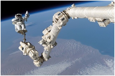
Figure 1: Canadarm2 with astronaut Stephen K. Robinson. Source: NASA 1
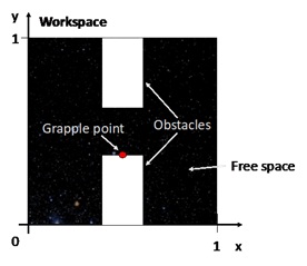
(a) An example of the workspace
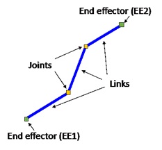
(b) The robot arm and its components
Figure 2
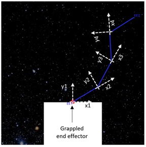
Figure 3: An illustration of the co-ordinate scheme of each joint on a 4-segment robotic arm.
end effector acts as a joint. Each joint is a rotational joint which means it can only rotate. A local coordinate system is attached to each joint. The co-ordinate system of the joint at the location of the grappled end effector, coincides with the coordinate system of the end effector. For the remaining joints, the x-axis is the line that coincides with the previous link. We define the angle of segment-i as the angle between link-i and the X axis of the coordinate system attached to joint-i. The joints are numbered relative to the grappled end-effector. Figure 3 illustrates the rotational joints. In some tasks, the links are telescopic and can change length (i.e. when the specified min and max segment lengths differ). This allows the robotic arm to more easily reach the grapple points.
Motion planning for CANADARM
This section describes what your program should do. Given the initial and goal configurations of the Canadarm robotic arm, as well as a map of the environment, your program must find a valid path from the initial to the goal configurations. A valid path means that when the Canadarm executes the path, it will satisfy the following requirements:
1. The path consists of primitive steps. In each primitive step, each joint of the robot arm cannot move more than 0.001 units (i.e. radians or arm length).
2. It will not collide with any of the obstacles 3.It will not collide with itself
4. The entire Canadarm robotic arm must lie inside the workspace
5. The angle between adjacent arm segments cannot be tighter than 15 degrees (i.e. angles 2, 3, 4... must be between -165? and +165?).
6. The segment lengths must be within the bounds specified in the input file (i.e. within min and max lengths)
7. Since a primitive step is very small, it is sufficient to satisfy requirements 2-4 at the beginning and end of each primitive step.
What is provided to you
We will provide supporting code in Python only, in the form of:
1.Support code to represent the problem ( problem spec.py, robot config.py, obstacle.py, angle.py)
2.A visualiser
3.A tester
4.Test cases to test and evaluate your solution
The support code can be found. Au- tograding of code will be done through Gradescope, so that you can test your submission and continue to improve it based on this feedback - you are strongly encouraged to make use of this feedback.
Your assignment task
You have been hired to develop Motion Planning software for a simplified version of the robotic arm. You will be graded on both your submitted program (Part 1) and the report (Part 2). These percentages will be scaled to the course weighting for this assessment item.
Part 1 - The programming task
Your program will be graded using the Gradescope autograder, using the COMP3702 testcases in the support code.
Interaction with the testcases and autograder
The input is a .txt file. To describe the format of this file, we first need to describe the format of a configuration.
Format of a configuration: A configuration is represented by n real numbers, where n is the dimension of the C-space. See example output.txt in the support code for an example of how this is formatted. Each number is separated by a space, and each group of numbers is separated by a semicolon:
• The first two numbers are the position of the origin of the grappled end effector in the workspace.
The next x numbers are the joint angles (ordered relative to the grappled end effector), with each joint angle defined in degrees.
The last x numbers are the lengths of each link (line segment) of the robot ordered relative to end effector 1.
Input format: The program you develop should accept an input file. The file contains information on the set-up of the robotic arm, the initial configuration, the goal configuration, and the environment. This input file uses comments (marked with ‘#') to label which values correspond to which parameters. The input parameters are as follows:
# Robotic arm details number of segments
min lengths for each segment (order from ee1) max lengths for each segment (order from ee1)
# Initial Configuration
initial grappled ee (either 1 or 2, representing ee1 or ee2) initial grappled eex, eey
initial angles from grappled ee +ve axis (degrees) initial segment lengths from ee1
# Goal Configuration
goal grappled ee (either 1 or 2, representing ee1 or ee2) goal grappled eex, eey
goal angles from grappled ee +ve axis (degrees) goal segment lengths from ee1
# Environment
number of grapple points
x, y for each grapple point
number of obstacles
x1, y1, x2, y2 for each obstacle
Output format: Your program should output the robot arm's path to a file with the following format.
1.The file consists of m +1 lines, where m is the number of primitive steps in your path.
2. The first line is the initial configuration.
3. The next m lines are the end configuration of each primitive step, where the final line should correspond to the goal configuration.
Examples of the input and output files are in the accompanying support code.
Part 2 - The report
The report tests your understanding of the methods you have used in your code, and contributes 40/100 of your assignment marks. Please make use of the report templates provided on Blackboard, be- cause Gradescope makes use of a predefined assignment template. Submit your report via Gradescope, in .pdf format (i.e. use "save as pdf" or "print-to-file" functionality), and named according to the format a2-[courseCode]-[SID].pdf. Reports will be graded by the teaching team.
Your report task is to answer the questions below:
Question 1.
Please define the Configuration Space of the problem and describe which method you use for searching in continuous space.
Question 2.
If you used a sampling-based method, describe the strategy you applied to develop each of its components (sampling strategy, connection strategy, checking if a configuration is valid or not, checking if a line segment in C-space is valid or not). Otherwise, please describe the equivalent details of your discretization method.
Question 3.
Which class of scenarios do you think your program will be able to solve and under what situation(s) do you think your program will fail? Please explain your answers.
Attachment:- Continuous motion planning in CANADARM.rar