Reference no: EM132411105
CIV 1175F Design of Tubular Steel Structukes Assignment, Department of Civil Engineering - University of Toronto, Canada
Q1. A W310 x 52 ASTM A992 Grade 50 beam is welded, after profiling of the flanges, at 90o to a HSS 219 x 9.5 ASTM A500 Grade C column. The beam flanges and web are fillet-welded to the HSS column on all sides. The cantilevered beam projects 2 metres from the column centre-line and serves as the support for a canopy over the entrance to a building in Toronto. By considering the beam-to-column connection only, determine the maximum uniformly distributed, static, factored gravity load to which the beam can be subjected.
Q2. A welded HSS K-shaped connection is composed of two branch members, both HSS 168 x 9.5, welded to a HSS 324 x 13 chord member, with each branch member inclined at 60o to the chord. All sections are CAN/CSA G40.20-04/G40.21-04 Grade 350W Class C. Static axial forces (one compression, one tension) are to be applied to the branches and the only chord force is that required to equilibrate the branch force components. The amount of gap or overlap or eccentricity is variable.
(a) Determine the maximum connection resistance (for any gap or overlap).
(b) Determine the connection resistance for a gap, g = 300 mm at the chord connecting surface.
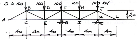
Q3. The planar, welded HSS truss shown below is supported by a pin at K and a roller at G, and is subjected to point loads at the top chord panel points which range cyclically from 0 to 100 kN, in the directions shown. The chord members are HSS 178 x 9.5 and all web members are HSS 152 x 6.4. All members are CAN/CSA G40.20-04/G40.21-04 Grade 350WT Class H. All member centre-lines are noding at the connections (zero eccentricity). The truss self-weight is 10 kN/metre.
(a) Determine the fatigue life of connection C.
(b) Determine the fatigue life of connection D.
5. A HSS 324 x 9.5 CAN/CSA G40.20-04/G40.21-04 Grade 350W Class H member is used as a composite column in a Canadian building, with an effective length of 4.0 metres. The HSS is filled with a carbonate, coarse-aggregate, plain, normal-density concrete, having a strength of f'c = 40 MPa. The column is subjected to an axial specified (un-factored) Dead Load (D) of 500 kN and an axial specified (un-factored) Live Load (L) of 500 kN. Assume a factored load combination of 125D + 1.5L. The column design is to conform with CSA S16-09. Determine the Fire Resistance of this composite column (in minutes). Solve using the NBCC 2005 Vol. 2 Division B Appendix D ("Fire Performance Ratings") method.
Q4. (a) The welded connection shown below has 3 circular HSS braces (branches) welded to a square HSS chord member. The pair of brace members above the chord is overlapped, and all brace members have a diameter that is half the chord member width. In order to correctly check the connection resistance, illustrate - on similar connection diagrams - how you would partition the forces on separate free body diagrams (as "pure K", etc.) in order to proceed with the check. Arrange the chord forces conservatively, so that they have the most punitive effect on connection resistance calculations.
(b) Two elevated walkways (4.5 metres apart) in an open hotel atrium, supported by square HSS beam members (labeled HSS), are to be suspended from above by two threaded steel rods, as shown below. The total load on each walkway = W. Two alternate construction arrangements are proposed, A and B, and for both the steel rods pass through holes drilled in the top and bottom of the HSS with a washer and nut used at each location C.
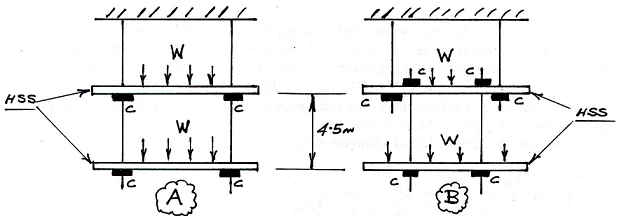
(i) Which configuration, A or B (if either), is more construction-friendly, and why?
(ii) Which configuration, A or B (if either), is more critical for the design of the tension rods, and why?
(iii) Which configuration, A or B (if either), is more critical for the loading on the square HSS member (in terms of local punching), and why?