Reference no: EM131151156
Characterization of Phase Frequency Response of Four Analog Filter Approximation Techniques Due the Excitation of Impulse, Step and Square Wave Signals
Abstract- The question often arises as to which filter approximation is superior to the others in terms of passband behaviours, stopband attenuation and the linearity of the phase response. This paper seek to answer this question by investigating the response of the four configurations when excited by an impulse, step and a square wave signal. Analysis is done in MatLab. It was found that butterworth is superior in ........., chebyshev type I is ........, Chebyshev type II is and finally BesselThompson is .......................
Index Terms-Impulse response, step response, square wane response, phase frequency response.
I. INTRODUCTION
ANALOG filters find applications in communication systems to filter out noise, in instrumentation to precondition the source signal, and in power systems to filter out the notorious odd harmonics [1, 2]. Different analog filter approximation will be better suited to different applications.................
basically talk about analog filters, their strengths and weaknesses. also briefly talk about this task and what you want to achieve. Cite key points from papers and books(books are discouraged)using IEEE referencing style.
II. METHODOLOGY
In this section, describe how you will carry out this task. You can use equations in s domain, convolution in time domain or matlab simulink to achieve your objectives. Refrain from appending your codes. Number your equations(not all are to be numbered) and reference them well as shown in equation 1 below for chebyshev type II response.
H(jω) = (€�Cn( 1 /ω )) / (√(1 +€�2Cn2 ( 1/ ω )))
Clearly outline your procedures.
III. SIMULATION RESULTS
Append your graphs here. Ensure that all curves depicting the same principle are on the same graph for ease of comparison e.g. magnitude frequency response of the four approximations, their phase frequency response e.t.c. Use

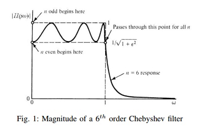
difference colours or line types to differentiate them. All figures should be centered and captioned and well referenced as shown in Figure 1 above.
IV. DISCUSSION OF THE SIMULATION RESULTS
You'll have six graphs in section III above: Magnitude response, phase response, impulse response, step response, square wave response and the poles location on the splane each with four graphs. Discuss each graph briefly and thoroughly and extract differences,similarities, uniqueness, e.t.c.
V. CONCLUSION
Your conclusion will be guided by the discussion. Comment on the shape of each of the response plots in the passband and stop band,Roll-off behavior of the different filter types, Phase response behavior of the three filters and the poles location. Relate the phase response and the poles lactation to the impulse response. At this point, now you can specify suitable applications for each approximation.
VI. GENERAL INSTRUCTIONS
Use font 24pt Times New Romans for the title and font 10pt Times New Romans for the body of the report. Page numbers to be at the Top right hand. This format, called IEEE format can be found online by the same name. Alternative, you can start learning LATEX.
This work, I know, is involving so give it your all. The report should be at least four pages and not more than six pages and strictly in this format. I expect at least ten references which are not books and not lecture notes. Kindly, refrain abstain from the vice of copy-pasting, either from your friend or from online sources.
REFERENCES
[1] E. S. Erdogan, R. O. Topaloglu, O. Cicekoglu, H. Kuntman, and A. Morgul, "Novel multiple function analog filter structures and a dual-mode multifunction filter," International Journal of Electronics, vol. 93, pp. 637-650, 2006.
[2] L. Zhongshen, "Design and analysis of improved butterworth low pass filter," IEEE, The Eighth International Conference on Electronic Measurement and Instruments , vol. 1, pp. 729-732, 2007.