Reference no: EM13841236
Consider the planar linkage shown below. The crank (link with length R) will turn counter-clockwise with a constant angular velocity (θ`).
The slider will experience a force (P) of 100 N directed to the left. Your task is to write a MATLAB program that
(a) Calculates the required input torque (T) and the magnitudes of the pin reaction forces (A, B, and C, along both x and y directions) for two full revolutions (0 ≤ θ ≤ 4Π) of the crank.
(b) You will then use your program to determine how changing the dimension H changes the average magnitudes of the pin reaction forces (refer to the free body diagram for the locations of these pins).
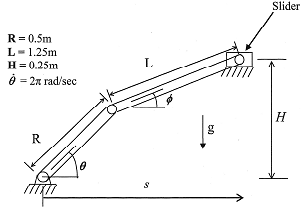
The first task is to determine the angle Φ and the slider position s given the crank angle θ The constraint equations that must be satisfied are:
Rsin(θ)+ Lsin(Φ)= H (1)
Rcos(θ)+ Lcos(Φ) = s (2)
You are required to solve these nonlinear equations for the unknowns the angle Φ and s using the Newton-Raphson method (as used in HW3).
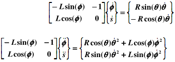
The next task is to solve for the (first and second) time derivatives of Φ and s, given θ (whose value is a constant, see in the figure on page 1). Equations (1) and (2) may be differentiated to obtain the following linear system of equations. You may use the MATLAB backslash operator "\"' to solve this set of equations.
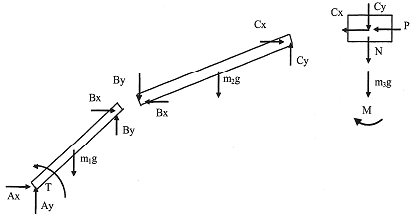
The next step is to consider the free body diagrams and obtain the corresponding dynamic equations. The free body diagram is below. Note that we are neglecting friction on the slider.
After simplification, the resulting dynamical equations in terms of the unknown reactions (Ax, Ax, Bx, By, Cx, Cy) and torque (T) can be expressed in matrix form as:
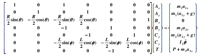
which can be solved using the MATLAB backslash operator "\", by taking the values for the coefficient matrix and right-hand-side vector from the above. Here, the link masses and moment of inertia are
m1 = 15 kg, m2 = 30 kg, m3 = 10 kg. 12 = (m2L2)/12.
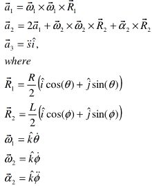
In the above matrix, we use the following vectors
Turn in a brief report containing the following:
(i) Title Page, including the title of the project and your name
(ii) Introduction and Objectives section
(iii) Program Design section (describe your program and the functions you used). Include all your M-files.
(iv) Results section, including properly labeled plots for the case where H = 0.25 m:
a. Φ and s vs. θ
b. Φ' and s' vs. θ
c. Φ" and s" vs. θ
d. |→A|,|→B|,|→C|, and T vs. θ
(v) A single plot displaying the average value of the magnitudes of the three pin reaction forces (A, B, and over the complete cycle for the range -0.6 ≤ H ≤ 0.6 m. Results for each pin should be displayed differently (for example. use a different color or a different line type). Include a legend on the plot to label the results for the three different pins.
(vi) Discussion of results, including your conclusion from part (v).