Reference no: EM133654659
Sensors and Sensing for Scientists
Assignment 1: Electronic basics, Ohms Law
Question 1: Calculating Resistance: An Automobile Headlight
What is the resistance of an automobile headlight through which 2.50 A flows when 12.0 V is applied to it?
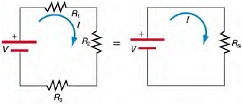
Question 2: Calculating Resistance, Current, Voltage Drop, and Power Dissipation: Analysis of Series Circuit
Suppose the voltage output of the battery in Figure is 12.0 V , and the resistances are R1 = 1.00 Ω, R2 = 6.00 Ω, and R3 = 13.0 Ω.
(a) What is the total resistance?
(b) Find the current.
(c) Calculate the voltage drop in each resistor, and show these add to equal the voltage output of the source.
(d) Calculate the power dissipated by each resistor.
(e) Find the power output of the source, and show that it equals the total power dissipated by the resistors.
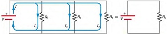
Question 3: Calculating Resistance, Current, Power Dissipation, and Power Output Analysis of a Parallel Circuit
Let the voltage output of the battery and resistances in the parallel connection in Figure be the same as the previously considered series connection: V = 12.0 V , R1 = 1.00 Ω, R2 = 6.00 Ω, and R3 = 13.0 Ω.
(a) What is the totalresistance?
(b) Find the total current.
(c) Calculate the currents in each resistor, and show these add to equal the total current output of the source.
(d) Calculate the power dissipated by each resistor.
(e) Find the power output of the source, and show that it equals the total power dissipated by the resistors.
Question 4: Calculating Resistance, IR Drop, Current, and Power Dissipation: Combining Series and Parallel Circuits
Figure shows the resistors from the previous two examples wired in a different way-a combination of series and parallel.
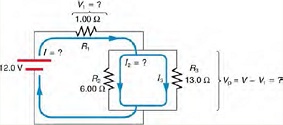
We can consider R1 to be the resistance of wires leading to R2 and R3.
(a) Find the total resistance.
(b) What isthe IR drop in R1?
(c) Find the current /2 through R2.
(d) What power is dissipated by R2?
Question 5: A negative temperature coefficient (NTC) thermistor has a resistance that depends on temperature i.e., R =f(T). The higher the temperature, the lower the resistance. The transfer function shown allows us to map resistance to temperature and vice versa.
A thermistor is placed into the circuit below. This circuit is called a voltage divider - it does just that, divides the input voltage up depending on the values of the two resistances in the divider.
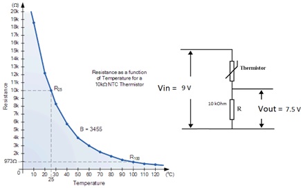
A voltage of 7.5 V is measured over the 10 k? resistor. Use Ohms law to determine the current through this resistor.
Determine the current running through the thermistor. Give your reasoning.
Using the principal that the supply voltage has been divided across thermistor and the fixed 10 k? resistor, what is the voltage drop over the thermistor?
Now knowing the voltage and current for the thermistor, calculate its resistance and use the transfer function to determine the temperature
Assignment 2 : Electronic Circuits
Question 1 Ohm's Law
Select Circuits Basics menu > Ohm's Law
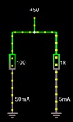
Adjust the voltage slider to 5V (right hand window).
Ensure left resistor = 100 Ω, right resistor = 1 Ωk
To change: Right click on the right resistor when it turns blue, and hit edit in pop up window. Change the resistance value as required.
a) What is the total current flowing from the 5V source?
b) Are the resistors in series or parallel?
c) Use Ohm's laws to determine the effective resistance of a single resistor that could replace the two resistors and not affect the current flow
d) What do you notice about the value of the equivalentresistance compared to R1 and R2
Question 2 Voltage divider
Take the circuit you have built for Task 1
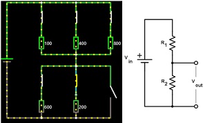
You will delete all the components in the left hand side and add a second resistor to the right hand arm. This makes a voltage divider. Its value should default to 1kOhm. Your circuit will look like this and is electrically equivalent to the circuit shown on the right. We'll call the top resistor R1 and the bottom resistor R2.
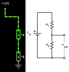
To calculate the voltage over R2, we can use the voltage divider formula Vout= Vin (R2/(R1 + R2)
a) Measure and record the voltage drop over and current through each resistance of 1 kOhm (R1 and R2)
b) Use the voltage divider formula to calculate the voltage over R1 and R2
c) Change R2 to 11 kOhm. Measure and record the voltage drop over and current through each resistance (R1 and R2)
d) Use the voltage divider formula to calculate the voltage over R1 and R2
Question 3 Wheatstone Bridge
Open Circuits > Other Passive Circuits > Wheatstone Bridge
In this section, we will combine two voltage dividers into a Wheatstone Bridge:
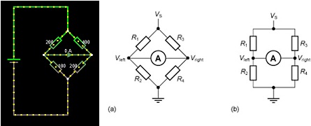
Adjust R4 in small steps (e.g., 0.05 ?) away from the value of 200 ? to about 200.3 ?.
Note the current in the galvanometer arm. Remember most galvanometers have a FSD of 20 ?A.
a) Build a table of values below and plot a graph:
b) Comment on the relationship of the galvo current to the value of R4
When the bridge is not balanced, adjust the value of R2 to null the current in the bridge (make current zero)
c) Record all the values of the resistors and check that the values of resistance satisfy the voltage divider relationship i.e., R2/R1 = R4/R3
d) Hover you cursor over point A and check the voltage you have calculated
Question 4: Series and parallel resistances
Open Circuits > Basics > Resistors
First close all open switches by clicking on them.
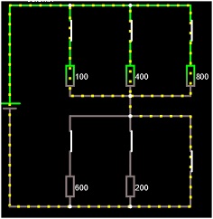
Press run.
a) Why is the current passing only through the wire in lower parallel resistance?
Bringing the cursors over each resistor in turn (100, 400 and 800) will give you information about voltages and current for each of the resistors.
b) What do you notice about the voltage drop over the 100, 400 and 800 ? resistances in the upper parallel combination?
c) Calculate the equivalent resistance of the upper parallel connection of resistors
d) How much current flows into the equivalent resistor?
e) Calculate the current following through each the 100, 400 and 800 ? resistors
f) Work out the power dissipated in each resistor
P=I2R
|
|
100 Ω
|
400 Ω
|
800 Ω
|
|
voltage
|
|
|
|
|
Current
|
|
|
|
|
Power
|
|
|
|
g) Sum the power dissipation
h) Use P=VI to calculate power deliver by battery
Now open the switch in the lower parallel circuit ie..remove the wire from the circuit:
i) Calculate the voltage drop measured across each of the two parallel circuits and ground. i.e., treat as voltage divider. To do this, you need to condense the circuit into two equivalent resistances in series and use voltage divider formula
Vout= Vin (R2/(R1 + R2)
Assignment 3 - Uncertainty and Errors
Question 1: A measurement of the block width is made as below
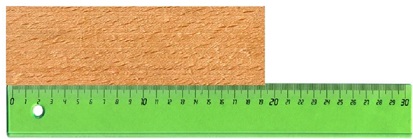
A Name the type of uncertainty/error in the following measurement of the block width (e.g., systematic or random etc.).
B What is the name for the origin of this type of error e.g. calibration error, manufacturing error etc...
C How will this type of uncertainty/error affect accuracy and precision?
Question 2 a) Write down the measurement value with associated uncertainty X ±ΔX for the four voltage readings A - D,
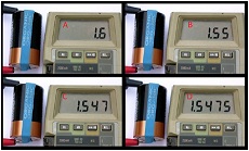
B Assume the digital display is staying steady in B over time (not changing). What can be determined about systematic error and the random error in the reading of 1.55?
C If the digital reading in B was jumping around say between a minimum of 1.53 and a maximum of 1.57, how should this measurement be reported? What does this tell you about the systematic and random error in the measurement?
Question 3 Give an example of each of the following systematic errors in a measurement system. Loading, operator, environmental, electrical offset, calibration
Question 4 Monitoring and programming sensor systems to identify anomalous behaviour in the sensor output is essential to data integrity. Often sensors contain code that allow them to self-diagnose their performance and any malfunction. An understanding of the performance of the sensor and the measurand is thus essential before the sensor is deployed. It is important to know how quickly the measurand can change naturally so that anomalous behaviour can be detected.
A.Sketch the output of a sensor that is becoming noisier in time. Sketch the output of a sensor that undergoes an abrupt change in output
B. Name some measurands and environments that might naturally show abrupt change and those that might not.
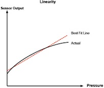
Question 5. Sensor manufacturers are often conservative in their spec sheets and often quote an overall accuracy and/or show errors band on transfer functions in the spec sheet that is larger than what can be achieved in practice. Manufacturer's error bands are based on worst case (which may not always be realised) and on the full span of the device.
In what instancemight a user achieve a better accuracy (and performance) than specification?
Question 6. The density of an object of mass M and volume V is calculated using:
ρ=mass/volume, ρ=M/V
Measurements give uncertainties of ΔM and ΔV in the mass and volume of an object respectively:
Mass = M ±ΔM , Volume = V ±ΔV ,
complete the following steps to derive an equation to calculate the relative (Δρ/ρ)and absolute uncertainty (Δρ)in the calculated density.
i.e., density = ρ±Δρ= ??
Relative error (mass) =
Relative error (volume) =
Relative error (density) =
Write this in terms of the preceding relative errors...
Absolute error (density) =
Write this in terms of the relative error in mass and volume and the calculated density ρ
e) Use your formula to calculate the density with uncertainty of an object that whose volume and mass is reported to be 100 ± 8 mL and 200 ± 5 g respectively.
Question 7: Calculate the uncertainty in the calculated power (P = VI) dissipated by a component when the voltage is reported to be 100 +/- 1 V and the current is reported to be 10.0 +/- 0.1 A.
Do this for two cases. The reported measurement and uncertainty is
a) statistically based (e.g., determined from n measurements, with n > 10
b) not statistically based (e.g., determined from a one-off measurement)
Which method yields the higher uncertainty in the calculated power?