Reference no: EM131902805
Homework Problems -
Problem 1 - Assume for this problem that the 69-kV system (Figure P9.1) is open and make the following calculations:
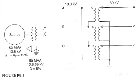
a. Calculate the fault current in the three phases for a solid a-phase-to-ground fault on the 69-kV terminals.
b. Calculate the three-phase voltages existing at the fault.
c. For this 69-kV ground fault, determine the currents flowing in the 13.8-kV system.
d. What are the voltages for the three phases at the 13.8-kV transformer terminals for the 69-kV fault?
e. Compare the fault current and voltage phasors on the two sides of the bank for the 69-kV ground fault.
Problem 2 - For the transformer bank of Problem 1, assume that phases A, B, C on the 13.8-kV side have 3000:5 CTs with taps at 1500, 2000, 2200, and 2500 A, and that the 69-kV circuits a, b, and c have 600:5 multi-ratio CTs with taps as indicated in Figure 5.11 (500, 450, 400, 300, 250, 200, 150, 100, and 50 A).
a. Show the three-phase connections for transformer differential relays to protect this bank.
b. Select suitable 69-kV and 13.8-kV CT ratios for this transformer differential application.
c. If the differential relay has taps of 4, 5, 6, and 8, select two taps to be used with the CT ratios selected in part b so that the percent mismatch is less than 10%.
d. With this application and setting, how much current can flow to operate the differential relay(s) if the phase-a-to-ground fault of Problem 1 part a is within the differential zone? How many of the three relays operate for this ground fault?
Problem 3 - The transformer bank (Figure P9.3) shown connected between the 13.8 and 2.4-kV buses consists of three single-phase units, each rated 1000 kVA, 13.8:2.4-1.39 kV.
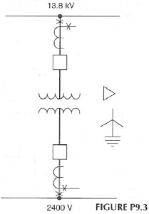
a. Connect a two-restraint type differential relay for protection of the transformer bank.
b. Select proper current transformer ratios and relay taps. Assume that the differential relay has ratio adjusting taps of 5:5 to 5:10 with the ratios of 1, 1.1, 1.3, 1.5, 1.6, 1.8 and 2.0. The CTs on the 13.8-kV breaker are 200:5 with 150, 100, and 50:5 taps, and on the 2.4-kV breaker; 2000/1500/1000/500:5 CTs.
c. If one of the single-phase transformers is damaged, can service be continued with the remaining two banks? If so, show the connections, including any modifications required for the differential relaying.
d. What is the maximum three-phase load that can be carried with any temporary connections?
Problem 4 - A 50 MVA transformer bank (Figure P9.4), wye-grounded to a 115 kV bus, and delta to a 13.8 kV bus, supplies power to the 13.8 kV system. Transformer breakers are available on both sides of the bank with 300:5 (115 kV side) and 2200:5 (13.8 kV side) current transformers. To ground the 13.8 kV systems, a 1200 kVA zig-zag transformer has been connected between the power transformer and the 13.8 kV bus and within the differential zone. For this arrangement as shown:
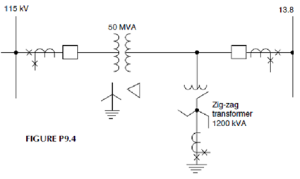
a. Connect three two-restraint type transformer differential relays to protect the 50 MVA bank using the two sets of CTs on the breakers. Only these are available.
b. The system X1 =X2 reactance to the 13.8 kV bus is 13% on 50 MVA, and the zig-zag bank reactance is 6% on its rating base. Calculate the current for a solid single-phase-to-ground fault on the 13.8 kV system. If the transformer differential relays have a pickup of 1.8 A, will they operate for a ground fault within the differential zone? What would you recommend for protection of the zig-zag bank?
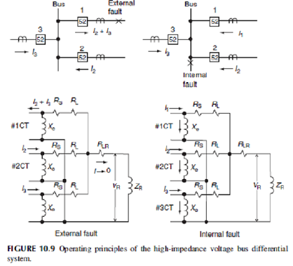
Problem 5 - High-impedance voltage-differential relays are to be applied to protect a three-breaker bus, as shown in Figure 10.9. The CTs are all 600:5 multi-ratio type with characteristics per Figure 5.11. For this application, determine the relay pickup setting voltage and the minimum primary fault current for which the relays will operate. The maximum external fault is 8000 A rms. Assume that the lead resistance RL = 0.510 Ω for the maximum resistance from any CT to the junction point. For the particular relays applied, the pickup setting voltage is
VR =1.6k(RS + pRL)IF/N volts
where 1.6 is a margin factor, k is a CT performance factor (assume k = 0.7 for this problem), p = 1 for three-phase faults and p = 2 for single-phase-to-ground faults, IF is the primary rms external maximum fault current, and N is the CT ratio. RS is the CT resistance. p = 2 should be used to determine the value of the VR setting. The maximum setting of the relay voltage element should not exceed 0.67 times the secondary exciting voltage of the poorest CT in the differential circuit at 10 A exciting voltage.
The minimum internal fault primary current to operate the relays is Imin = (nIe + IR + IT)N primary amperes
where n is the number of circuits, Ie is the exciting current of the individual CT at the pickup voltage, IR is the relay current at the pickup setting voltage and IT is the current required by a high-voltage protective device across the relay coil (not shown in Figure 10.9). For this problem, assume IT = 0.2 A. The relay impedance and generally negligible resistance of the leads from the junction to the relay is 1700 Ω. nIe is applicable in this problem since all three breaker CTs are the same; otherwise, this is a summation of the different CT exciting currents at the VR pickup voltage.
Problem 6 - A feeder circuit is added to the bus of Problem 5. Making a four-circuit bus. The new breaker has the same type 600:5 multi-ratio CTs. With this addition, the maximum external fault current increases to 10,000 A rms. All other circuit values remain the same. For this change, calculate the relay pickup setting voltage and the minimum primary fault current for which the relays will operate.
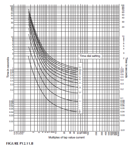
Problem 7 - The 12.5 kV distribution feeder (Figure P12.1) has two taps. One is protected by three oil circuit reclosers with 70/140A coils set as in Table P12.1. The other tap is a single-phase circuit protected by one 30A fuse operating as shown in Table P12.2. The data for the 46 kV fuse is in Table P12.3. The phase and ground relays are very inverse time over-current with instantaneous units. Their time over-current characteristics are shown in the typical curve s of P12.11. Fault currents are in amperes at 12.5 kV.
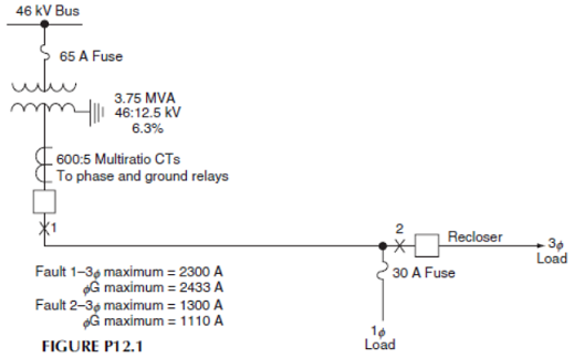
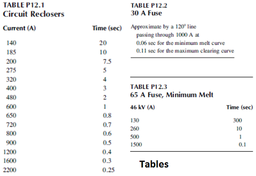
a. Determine the 46 kV fuse time-current characteristics in terms of 12.5 kVA for 12.5 kV three-phase, phase-to-phase and phase-to-ground faults. Draw these high-side fuse curves along with the recloser and 30 A fuse curves on time-current log paper, such as K & E 48 5257, with 12.5 kVA as the abscissa and time in seconds as the ordinate.
b. Select a suitable ratio for the current transformers to the phase and ground relays.
c. Set and coordinate the phase and ground relays. Provide a minimum 0.2sec coordination interval between the re-closers and the relays, and a minimum 0.5sec between the 46kV fuse and the relays. Specify the time-over-current relay tap selected (available taps are 1, 1.2, 1.5, 2, 2.5, 3, 3.5, 4, 5, 6, 7, 8, 10), the time dial, and the instantaneous current pickup for both phase and ground relays. Plot the coordination on the curve of part 1.
Problem 8 - Blackburn Problem
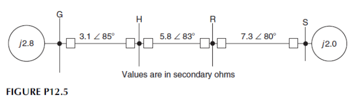
a. Apply and set distance-type relays at Stations H and R for the protection of line HR in the system in Figure P12.5. Set zone 1 units for 90% of the protected line, zone 2 to reach 50% into the next line section beyond the protected line, and zone 3 for 120% of the next line section.
b. Plot this system on an R X diagram with the origin at bus H. Plot the relay settings of part 1 using mho-type characteristics. The mathematical formula for a circle through the origin or relay location is where Zs is the relay setting at 75o.
c. What is the maximum load in MVA at 87% pf. that can be carried over line HR without the distance relays operating? Assume that the voltage transformer ratio RV = 1000 and the current transformer ratio Rc = 80.
Problem 9 - The 60 mile, 115 kV line GH (Figure P12.8) is operating with the voltages at each end 30o out of phase when a three-phase fault occurs at 80% of the distance from bus G. This fault has 12 Ω arc resistance. The currents flowing to the fault are as shown and are in per unit at 100 MVA, 115 kV.
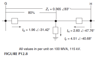
a. Determine the apparent impedance seen by the distance relays at G for this fault.
b. Determine if the zone 1 mho unit at G set for 90% of the line GH can operate on this fault. Assume that the angle of the mho characteristic is 75o.
c. Determine the apparent impedance seen by the distance relays at H for this fault.
d. Determine if the zone 1 mho unit at H set for 90% or the line GH can operate for this fault. Assume that the angle of the mho characteristic is 75o.
Textbook - Protective Relaying Principles and Applications, Third Edition by J. Lewis Blackburn and Thomas J. Domin.
Attachment:- Class Notes.rar