Reference no: EM133121786
CVE80004 Advanced Concrete Design - Swinburne University of Technology
Assignment Strut and tie method
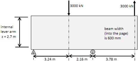
Question 1. Draw at a scale of 1:100 a layout of major and minor struts and ties that meet the requirements for a deep beam, using the internal lever arm and shear spans shown. Dimension all node positions. Show tension members as solid lines and compression members as dashed lines. Show the value and direction of the loads and reactions.
Question 2. Label the nodes on the diagram in (1) above starting with A for the top left node, continue from left to right across the top row, then continue from left to right across the bottom row (only label nodes not members).
Question 3. Analyse this layout to find the forces in each member. Write the value of the force in each member on the diagram you made in (1) above.
Question 4. Calculate the steel cross section area for the ties.
Question 5. Calculate the minimum dimensions for the cross section of the struts.
Question 6. Calculate the minimum dimensions of each node, such that it is hydrostatic, and check the node capacities (ignore any eccentricity of the forces acting on the node).
Question 7. Select a suitable width for the bearing plates at the load points and support points in compression.
Question 8. Draw the layout of the strut and tie model at a scale of 1:50 (it will be sideways on an A4 page. Draw the nodes and struts to scale, and show the length of each node face on this diagram. Show the reinforcing area required for each tie (bar numbers and size are not required). You are not required to show the overall concrete outline and size of the beam in this drawing.
Attachment:- Advanced Concrete Design.rar