Reference no: EM132241728
Question 1: The full-bridge inverter in Figure 6.3a has an RLC load with R = 6.5 Ω, L = 10mH, and C = 26 μF. The inverter frequency, fo = 4130Hz, and the dc input voltage, Vs = 220V.
(a) Express the instantaneous load current in a Fourier series. Calculate (b) the rms load current at the fundamental frequency I1; (c) the THD of the load current; (d) the average supply current Is; and (e) the average, rms, and peak currents of each transistor.
Multisim Simulation: Simulation of Problem 6.3
Question 2: A single-phase full-bridge inverter, which uses a uniform PWM with two pulses per half-cycle, has a load of R = 4Ω, L = 15 mH, and C = 25µF. The de input voltage is Vs = 220V. Express the instantaneous load current io(t) in a Fourier series for M = 0.8, f0 = 60Hz.
Question 3: The single-phase half-bridge inverter is operated at 1 kHz and uses a staircase modulation shown in Figure P6.23 with seven pulses per half-cycle for voltage control. Plot the fundamental component. distortion factor, and THD against the modulation index M.
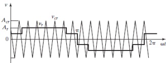
FIGURE P6.23 [26]
Question 4: The parameters of the boost inverter in Figure 6.40b is operated at a duty cycle k = 0.6. Find (a) the dc voltage gain Gdc(b) the ac voltage gain and (c) the instantaneous capacitor voltages va and vb.