Reference no: EM132223959 , Length: 4 pages
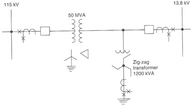
Question 1: A 50 MVA transformer bank (Figure P9.4), wye-grounded to a 115 kV bus, and delta to a 13.8 kV bus, supplies power to the 13.8 kV system. Transformer breakers are available on both sides of the bank with 300:5 (115 kV side) and 2200:5 (13.8 kV side) current transformers. To ground the 13.8 kV system, a 1200 kVA zig-zag transformer has been connected between the power transformer and the 13.8 kV bus and within the differential zone.
For this arrangement as shown:
a. Connect three two-restraint type transformer differential relays to protect the 50 MVA bank using the two sets of CTs on the breakers. Only these are available.
b. The system X1 =X2 reactance to the 13.8 kV bus is 13% on 50 MVA, and the zig-zag bank reactance is 6% on its rating base. Calculate the current for a solid single-phase-to-ground fault on the 13.8 kV system. If the transformer differential relays have a pickup of 1.8 A, will they operate for a ground fault within the differential zone? What would you recommend for protection of the zig-zag bank?
Question 2: High-impedance voltage-differential relays are to be applied to protect a three-breaker bus, as shown in Figure 10.9. The CTs are all 600:5 multi-ratio type with characteristics per Figure 5.11. For this application, determine the relay pickup setting voltage and the minimum primary fault current for which the relays will operate. The maximum external fault is 8000 A rms. Assume that the lead resistance RL = 0.510 Ω for the maximum resistance from any CT to the junction point. For the particular relays applied, the pickup setting voltage is
VR = 1.6k (Rs + pRL)IF/N Volts
where 1.6 is a margin factor, k is a CT performance factor (assume k = 0.7 for this problem), p = 1 for three-phase faults and p = 2 for single-phase-to-ground faults (Figure 5.10), IF is the primary rms external maximum fault current, and N is the CT ratio. RS is the CT resistance. p = 2 should be used to determine the value of the VR setting. The maximum setting of the relay voltage element should not exceed 0.67 times the secondary exciting voltage of the poorest CT in the differential circuit at 10 A exciting voltage.
The minimum internal fault primary current to operate the relays is
Imin = (nIe + IR + IT)Nprimary amperes
where n is the number of circuits, Ieis the exciting current of the individual CT at the pickup voltage, IR is the relay current at the pickup setting voltage and IT is the current required by a high-voltage protective device across the relay coil (not shown in Figure 10.9). For this problem, assume IT = 0.2 A. The relay impedance and generally negligible resistance of the leads from the junction to the relay is 1700 Ω. nIe is applicable in this problem since all three breaker CTs are the same; otherwise, this is a summation of the different CT exciting currents at the VR pickup voltage.
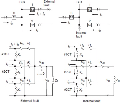
Figure 10.9
Question 3: A feeder circuit is added to the bus of Question 2, making a four-circuit bus. The new breaker has the same type 600:5 multi-ratio CTs. With this addition, the maximum external fault current increases to 10,000 A rms. All other circuit values remain the same. For this change, calculate the relay pickup setting voltage and the minimum primary fault current for which the relays will operate.