Reference no: EM132970388
SEM302 Advanced Stress Analysis - Deakin University
Problem Solving Task 1
Strict Enforcement of Guidelines for Late Submission of Assessment
The University guidelines for late submission are clearly laid out in the ‘T2 2021 Your rights and responsibilities as a student in this Unit' guide under Unit Information in this Cloud Deakin (Unit) site. These guidelines will be strictly enforced in this Unit. While it is important that you familiarise yourself with the entire document, some of the key aspects of the guidelines have been highlighted below:
• A 5% per day deduction (from the total marks) will be enforced for up to 5 days for late submissions.
o For electronic submissions, a ‘day' includes weekend and public holiday days.
• Assessment submitted after 5 days will not be accepted and a result of 0 will be awarded.
o Some assessment, for practical purposes (for example a quiz or presentation), may have a fixed deadline and late submissions therefore immediately attract a mark of 0%. These cases will be made clear to students prior to the deadline.
• Outside of exceptional circumstances, applications for extension should be received 72 hours
before the submission deadline.
• Applications for extensions must be supported by evidence and demonstrate why it would prevent you from completing the assessment on time.
o Note: a medical certificate showing that you were unwell for a short period of time would not be considered sufficient grounds to grant a submission deadline extension in most cases.
o Requests for extensions on the grounds of feeling stressed or over-worked will typically not be granted. It is your responsibility to manage your time and your assessment.
o If you have reasonable grounds for an extension in the lead-up to a submission deadline, the Unit Chair, at their discretion, may grant your request. In additional to providing sufficient evidence to substantiate why you cannot meet the deadline, you may also be asked to show evidence of progress with the assessment. i.e. that you have completed a reasonable amount of the assessment (and can show this by supplying a copy of the progress made). The evaluation of the extent of the progress and whether or not an extension request is granted is up to the discretion of the Unit Chair.
o In general, all applications for an extension should be supplemented with evidence of progress with the assessment.
• If you believe that your case warrants an extension, you MUST submit a request for extension using the extension request tool on the unit site. This can be accessed under the "Assessment" tab.
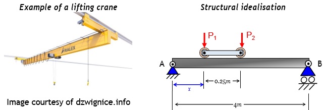
Question 1: Prismatic Beam Design: Variational Loading
You have been tasked with designing a beam to support a lifting crane. The applied load is offset from the centre of the carriage used to mount the crane to the overhead beam. Therefore, the loads applied to the two axels, P1 and P2, differ. The position of the crane can vary (dependent on the variable, x, shown below).
|
Material Properties (Beam A-B)
Symbol Value Units
|
Loads
P1 = 0.75P
P2 = P
|
|
E 69.0 GPa
v 0.28 N/A
P 7.19 Mg/m3
σallow 330.0 MPa
τallow 110.0 MPa
|
Your task is to analyse the structure. To do this you will:
a) Determine an expression for the vertical reaction at Point A.
Note: this will be a function of x, where 0 ≤ x ≤ 3.75m.
b) Find the position of x that results in the maximum bending moment
c) If the beam has a rectangular cross-section (200mm high X 50mm wide), what is the maximum load, P, that can be applied to lifting crane? Apply a safety factor of 2 when performing this calculation.
Question 2: Combined Stresses and Superposition
A circular pier of width, d, must be designed to withstand a concentrated load, P, applied at the edge of the section. The material used to fabricate the pier is sensitive to tensile loading, hence, the allowable tensile strength (σT) must be used to design the pier. It can safely be assumed that the pier is sufficiently short to prevent buckling. As a consultant engineer you have been tasked with evaluating the circular pier and two alternative designs namely a rectangular pier and a crossed pier. It should be noted that the width of the two alternative designs, b, is unknown and you are tasked with designing the piers and evaluating the stress state.
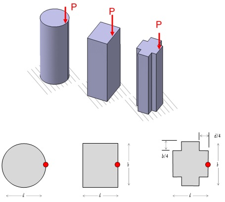
The geometry of the three cross-sections (left) circular (middle) rectangular (right) crossed. It should be noted that all cross-sections are symmetrical about their centroid. The red dots represent the location of the applied force, P, for each pier.
The magnitude of the applied load, P, is 150kN.
|
Symbol
|
Value
|
Units
|
|
E
|
100.0
|
GPa
|
|
σallow(tension)
|
250
|
MPa
|
|
τallow
|
150.0
|
MPa
|
|
ρ
|
4.00
|
g/cm3
|
In order to compare the three concepts, you will:
a) Design the circular pier (diameter, d) to resist the maximum applied tensile stress.
Hint: to make this task easier you can use the principal of superposition to calculate the axial and bending stresses separately and sum the critical stresses to obtain the resultant stress.
b) Based on your design calculate the maximum tensile and compressive stresses in the circular pier.
c) Design the width, b, of the rectangular pier so the maximum tensile stress is equal to the maximum tensile stress in the circular pier. The dimension d is taken from your circular pier design.
d) Calculate the width of the crossed pier, b, so the maximum tensile stress is equal to the maximum tensile stress in the circular pier. The dimension d is taken from your circular pier design. Ensure that you document the method used to determine the moment of inertia I (and/or section modulus, S)
e) Evaluate the maximum compressive stress in each of the three designs and determine which design has the largest compressive stress.
Question 3: Deflection of prismatic and non-prismatic beams
You are tasked with analysing a cantilever beam with a cross-section that tapers in both width and height. The length of the beam is, L, and the cross section at the tip (x=0) has a width of 2b and a height of b. At the fixed end (x=L) the cross-section has a width of 4b and a height of 2b. Your client is interested in understanding the maximum deflection of the beam.
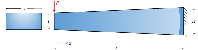
Side view of the tapered beam. The cross-section on the left-hand side of the image represents the tip of the beam (x=0) with a width of 2b and a height of b.
The parameters related to the problem:
|
Symbol
|
Value
|
Units
|
|
b
|
100.0
|
mm
|
|
L
|
2.0
|
m
|
|
P
|
2.0
|
kN
|
|
E
|
100.0
|
GPa
|
|
σallow(tension)
|
250.0
|
MPa
|
|
τallow
|
150.0
|
MPa
|
|
ρ
|
4.0
|
g/cm3
|
In order to assess the design, you will:
a) Use the method of integration to determine the maximum deflection of the beam assuming that the cross-section is constant along the length of the beam (width 2b and height b). Assume that x=0 coincides with the tip of the beam (as shown in the image).
b) Use the moment area method to determine the maximum deflection of the beam assuming that the cross-section is constant along the length of the beam (width 4b and height 2b).
c) Calculate the maximum deflection of the tapered cantilever beam. Note: you must account for the changing cross-section of the beam along the length.
Attachment:- Advanced Stress Analysis.rar