Reference no: EM135268
Part I.
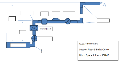
As given in the sketch, water at 20° C is being pumped from a lower tank and discharged into the atmosphere 10 meters above the level of the tank. The flow rate is 1200 liters/minute. There is a negligible amount of 5 inch schedule 40 commercial steel pipe between the tank and the pump containing a square edged entrance, a ball check valve, two standard elbows and a strainer with a loss coefficient, K, of 3.0. The pump suction is three (3) meters above the level of the tank. The discharge pipe is 50 meters of 3.5 inch schedule 40 commercial steel pipe, containing a globe valve, a straight flow tee and two standard elbows.
a) Calculate the head provided by the pump (m).
b) Calculate the brake power required if the pump efficiency is 75% (kW).
c) Calculate the net positive suction head available (NPSHA) if the atmospheric pressure is 100 kPa. (m)
Part II.
You Already calculated one point of HA at various flow rates for the system curve. Develop the system curve by calculating HA at various flow rates for the system given, and plot the values on attached Pump Characteristic Curve and determine
a) The flow rate (1min) ________, head (m), ___________and BHP (kw) __________at which this pump will operate in the sytem.
b) With the pump curves given, develop an efficiency curve for the pump and determine the maximum efficiency and the efficiency at which the pump system will operate. ____________
