Reference no: EM133256599
Programmable Logic Controllers
Assignment Theory
Question 1. (a) By using a truth table or otherwise, show that the expressions below are equivalent
(AB‾ + BC‾ + AC‾)‾ = ABC
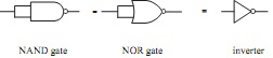
(b) Show by plotting truth tables that the following 2 input gates are equivalent to an inverter
Question 2. Draw the logic circuit to represent the following Boolean expression using only two input NAND gates.
F = ((AB.BC‾)‾.(A‾C)‾)‾
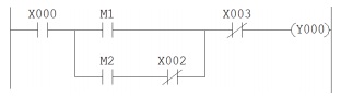
Question 3. Write down the Boolean expression for the following ladder diagram. X denotes a switched input, M represents an internal relay contact and Y000 is a motor contact.
Question 4. (a) Convert the following Hex numbers to binary and add them. Express your final answer in HEX
2A7E + 45CB
(b) Write down the 2's complement of the following binary number
10110000
(c) Convert the following numbers to binary and evaluate using the 2's complement method. Leave your answer in binary form.
68 - 145
(d) Write down the BCD form of decimal 936.
Question 5. Describe two advantages of a PLC based system over a purely relay based one.
Question 6. Referring to the opto-triac output circuit shown below.
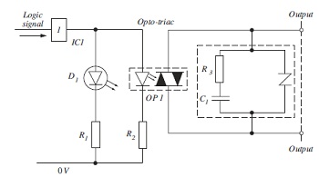
Given the following parameters
Logic voltage = 3.3V
D1 forward voltage drop = 1.8V D1 operating current = 10mA
Opto-triac minimum operating current 2mA Opto-triac LED forward voltage drop 1.6V
Calculate suitable values for R1 and R2, show all your working.
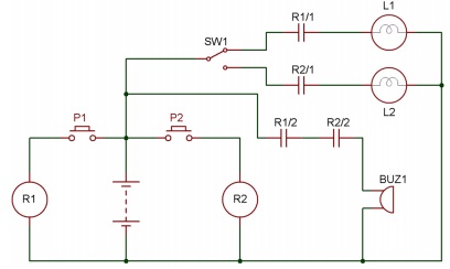
Question 7. Convert the following circuit diagram to PLC ladder logic, giving full list of I/O and any internal logic used. Describe the operation.
Question 8. Explain the basic operation of a PLC scan cycle.
Question 9. (a) Describe the operation of the ladder circuit shown below. The ladder uses the Mitsubishi standard of M for internal relays, Y for external output and T for timer.
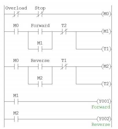
(b) What type of application could this circuit be used for?
(c) What is the purpose of the timers?
Question 10. What is the difference between opcodes and operands?
Question 11. (a) An A/D conversion has an 8 bit resolution and an input range of 0~5V. A second convertor has an input range of 0~24V and a 10 bit resolution. Calculate the digital output value in Hex that will represent 3V in both cases.
(b) State which of the two convertors in (a) is more accurate and explain why.
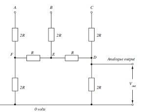
Question 12. For the digital to analogue convertor circuit shown below and taking C as the most significant bit, construct a table of all the possible output voltages given a supply voltage of 24 volts. Show all calculations.
Programming Assignment
EXERCISE 1 - ANNUNCIATOR
In industry, plant conditions are monitored and, if there are problems, it is necessary to have some way of indicating such problems. An indicator system of this type is called an Annunciator. A typical alarm system uses the following sequence to indicate a plant alarm condition to an operator.
(i) System healthy - no indication.
(ii) System in alarm - a flashing Amber light and audible alarm. FIGURE 1 shows the graphics simulation of the alarm system.
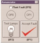
FIG. 1 Annunciator Simulation
1. If the operator presses the ACCEPT button when the plant is in alarm (ii above), the audible alarm stops and the flashing Amber light changes to permanently ‘ON'.
2. If the plant drops out of the alarm condition before the ACCEPT button is pressed, the panel will show a flashing Green light. The Audible alarm and Amber light will go ‘OFF'.
3. If the ACCEPT button was pressed when the plant is healthy as in 2 above, the flashing Green light will go ‘OFF'.
4. There should be a LAMP TEST button which, when pressed, will light all lamps and sound the audible alarm.
5. Write a program that will operate the Alarm Simulation, using the following inputs and outputs and whatever Timers and Flags are required.
IP0 = Plant alarm condition OP0 = Amber Lamp
IP1 = Operator accept button OP1 = Green Lamp
IP2 = Lamp test OP2 = Audible Alarm
6. Use the comments facility to describe the operation of the program.
EXERCISE 2 - CAR PARK
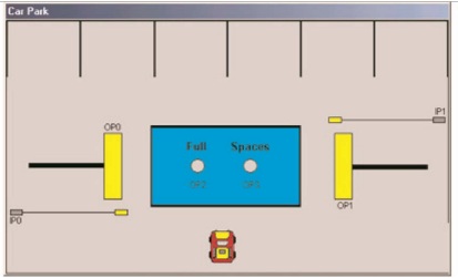
FIG. 2 Car Park Simulation
Consider the above diagram, FIGURE 2, of the car park. The object of this assignment is to write a program to operate the barriers to allow the cars in and out.
As you can see there is a box in which there are two condition lights for when the car park is full, and when there are spaces.
The entrance to the car park is on the left hand side. When a car drives into the car park there is a sensor that detects the car and this should cause the barrier to be opened to allow the car in.
On the right hand side is the exit. When a car leaves the car park it will activate a sensor inside the park to open the exit barrier.
Both the entry and exit barriers will need to be in the up position long enough to allow the cars to enter or leave the car park. The inputs and outputs are listed as follows:
IP0 = Entry Sensor OP0 = Entry Barrier
IP1 = Exit Sensor OP1 = Exit Barrier
OP2 = Full Light OP3 = Spaces Light
When writing the program it is necessary to observe the following conditions. When the car park is not full the Spaces light should be ‘ON'. When the car park is full the Full light should be ‘ON'. As a car enters or leaves the car park the entry and exit barriers have to be held in the up position long enough to allow the cars to pass under the barriers.
When the program is complete and the car park graphic is displayed in Simulation mode the program is operated by pointing at the car and clicking the mouse button. You will see directional pointers left and right so point at and click the direction you wish the car to travel. When you wish a car to leave the car park point at the one you wish to leave the park and click. You should explain the operation of the program, using the documentation facility.
EXERCISE 3 - ELEVATOR
FIGURE 3 shows the graphic simulation of the Elevator.
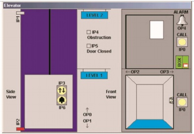
FIG 3 Elevator Simulation
The object of this assignment is to write a program that will drive the Elevator from one floor to the other.
The list of inputs and outputs are as follows.
IP0 External Elevator call button OP0 Elevator motor UP
IP1 Elevator on level 2 sensor OP1 Elevator motor DOWN
IP2 Elevator on level 1 sensor OP2 Elevator door motor OPEN
IP3 Internal Elevator button OP3 Elevator door motor CLOSE
IP4 Door obstruction sensor OP4 Alarm
IP5 Lift door closed sensor IP6 Lift stuck alarm button
The operation of the elevator is as follows: Assuming that the elevator is at level 1, (IP2 energised), there are two options;
1. The elevator could be called from level 2 by the external call button IP0 being pressed. The elevator doors should then close via OP3, once closed IP5 (doors closed sensor) should energise. At this point the elevator should start to move up via OP0 (elevator motor UP). Once the elevator reaches level 2, IP1 would energise and this should stop the elevator motor. After a short pause the elevator doors should open via OP2.
2. The elevator could also be operated from level 1 via the internal button IP3. The elevator doors would then close (OP3) energising IP5 (doors closed sensor). The elevator should then move up to level 2 via OP0. Once level 2 sensor IP1 energises, the elevator doors can then open via OP2.
Note: When the elevator is on level 2 it will be necessary to drive the elevator down to level 1 using OP1 (elevator motor DOWN).
Other facilities:
(a) Alarm: Should the elevator get stuck between floors or the doors not open, then by pressing IP6 the alarm OP4 should operate.
(b) Door Obstruction: If the doors are obstructed the elevator motors OP0and OP1 should be disabled. You can test this by clicking on the box and obstructing the doors.
When writing the program use the inputs and outputs as listed, use any flags, timers, and counters as required. As usual use the comments facilities to document your program.
EXERCISE 4 - DRINKS MACHINE
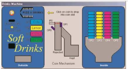
FIGURE 4 shows the graphics simulation of the drinks machine.
FIG. 4 Drinks Machine Simulation The list of inputs and outputs is as follows:
The operation of the Soft Drinks Machine is as follows;
When a coin is clicked on with the mouse it is placed into the slot, it then operates the coin sensor IP0. This should operate OP0 (coin hold solenoid), which will hold the coin in place. At this point either a drink is selected or the coin rejected.
The rejection of a coin is by operating IP5, which should reset OP0 allowing the coin to fall into the rejection box. If a coin is rejected, pointing the mouse at the coin and clicking resets the machine.
If a drink is selected by the operation of one of the drink select buttons, OP1 (coin accept solenoid) should operate. This allows the coin to fall into the Kept box. Once the coin has dropped into the box, the solenoid corresponding to the selected drink should operate, allowing the drink to be dispensed.
Once the selected drink has been dispensed, clicking the coin will reset the machine.
Important Notes: When writing the program you must ensure that:
(a) The coin cannot be rejected once a drink has been selected.
(b) Selecting a drink disables all of the other drink buttons.
As usual, use the listed inputs and outputs and any flags, timers, and counters you require to complete the assignment. Use the documentation facilities to describe the program function.
EXERCISE 5 - PACKING LINE
The packing line simulation is shown in FIGURE 5.
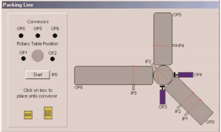
FIG. 5 Packing Line Simulation
This exercise involves programming the simulator of FIGURE 5.The packing line carries boxes of different sizes that need to be separated at the end of the first conveyor. Which direction the boxes travel at the end of the first conveyor should be decided by using the input sensors IP1 and IP2. If the box is a short one, the inputs will only be energised one at a time. If the box is a long one then, for a short period, both inputs will energise at the same time.
When the box reaches the end of the first conveyor, which is driven by OP0, it will come to rest on the circular plate and will energise the sensor IP3 (the first conveyor will also stop). The plate will then turn either to the left or the right depending on the length of the box. OP2 turns the plate to the right; OP1 turns the plate to the left.
Once the plate has turned, the box will be pushed on to the next conveyor by either piston OP4 or OP3. Output OP6 drives the left-hand conveyor and output OP5 drives the vertical conveyor. Inputs IP4 and IP5 are sensors which detect the boxes on the conveyors as they are transported to the correct loading areas depending on their length. Once the boxes pass these sensors there should be a short delay and the respective conveyor should stop.
Write a program to carry out the previously described operation and, as with the previous assignments, use the documentation facilities. When the program is complete, test its operation using the simulation package. To use the graphic simulation click on a box which, will place the selected box on to the first conveyor then operate the start switch IP0.
The following is a list of the inputs and outputs, in addition to this list use any of the Flags, Timers, and Counters that you require in your program.
IP0 Start button OP0 Loading conveyor
IP1/2 Box length sensors OP1 Turns direction plate to the
left
IP3 Box on the direction plate OP2 Turns direction plate to the
sensor right
IP4 Box on the vertical sensor OP3 Push the box on to the vertical conveyor
IP5 Box on the left conveyor OP4 Push the box on to the left
sensor conveyor
OP5 Vertical conveyor OP6 Left hand conveyor
EXERCISE 6 - BOTTLING PLANT
FIGURE 6 shows a graphic of the Bottling Plant Simulation. It represents the area where the bottles are filled and then sent on to the packing area. The object of this assignment is to write a program that will control the bottling plant simulation. The program should be fully documented.
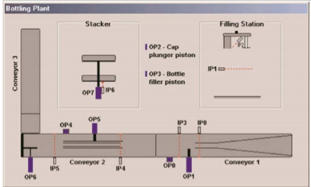
FIG. 6 Bottling Plant Simulation The Inputs and Outputs are listed below:
IP0 Bottle stop sensor OP0 Conveyor 1
IP1 level sensor OP1 Stop bottle piston
IP2 Sol 4 limit switch OP2 Cap plunger piston
IP3 Bottle clear OP3 Bottle filler piston
IP4 Bottle in winder sensor OP4 Conveyor 2
IP5 Counter sensor OP5 Cap winder piston
IP6 Stacker piston limit switch OP6 Stacker piston
OP7 Stacker to conveyor 3
A little thought must first be given to understanding the bottling process. With reference to FIGURE 6, conveyor 1 runs continuously and is fed one bottle at a time. Each bottle travels along the conveyor and is guided to the position where it is filled and capped. A sensor, IP0, detects when the bottle reaches the position and a piston controlled by OP1 is activated and stops the bottle. With the bottle in this position, the filler nozzle piston is activated by OP3 which pushes the nozzle into the neck of the bottle. As it goes into the bottle, a valve automatically opens allowing the liquid to be released into the bottle. This is simulated in the ‘Filling Station' section.
When the liquid in the bottle activates the level sensor IP1, OP3 de-activates, lifting the nozzle out of the bottle. A few seconds after the nozzle has cleared the bottle, the cap plunger piston OP2 activates, pushing a cap on to the bottle. At the end of the piston travel is a limit switch IP2 which operates as the cap is placed on the bottle. This switch de-activates OP2 retracting the piston and leaving the cap on the bottle. It also de-activates OP1 releasing the bottle stop piston. IP3 will see the bottle as it leaves the filling area.
At this point the cap just rests on the filled bottle and must still be screwed tight. To achieve this, the bottle passes onto conveyor 2 where it is guided into the ‘cap winder' area. As it enters this area, a sensor (IP4) detects its presence and this activates the cap winder piston via OP5. The operation of this piston closes the guide just enough to put pressure on one side of the cap and, as the bottle travels down the conveyor; this causes the cap to rotate and tighten on the bottle.
When the bottle reaches the end of conveyor 2 it activates the Counter Sensor IP5. This sensor has three functions:
1. It deactivates the cap winder piston OP5.
2. It counts the number of bottles onto the Stacker.
3. When three bottles have passed onto the stacker it operates the stacker piston via OP6 and this pushes the three bottles clear to allow the next three bottles onto the stacker.
When 9 bottles are on the stacker it will operate the piston OP7, which lowers the stacker platform to conveyor 3 as shown in the stacker section of the FIGURE 6. At this point, the 9 bottles are pushed onto conveyor 3 but the operation of this, and conveyor 2, is taken care of automatically so it is not the concern of your program.
When the stacker piston extends it operates a limit switch at the end of its travel de-activating the piston.
EXERCISE 7 - INDUSTRIAL CONTROL SIMULATOR
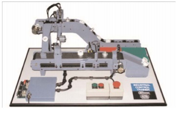
FIG. 7 Bytronic Industrial Control Trainer (ICT3)
The Industrial Control Trainer is a mini-production line trainer. The system has been designed to realistically represent a component sorting, assembly and inspection process that can be controlled from virtually any Programmable Logic Controller with relay outputs or a PC with a suitable interface card. In principle, the unit is designed to sort an aluminium ‘peg' from a plastic ‘ring', then assemble these two components and check for correct assembly. The components are initially randomly placed on the chain conveyor and are lifted to a higher level. When the higher level is reached, the plastic components are detected by an infra-red emitter/detector and ejected by a solenoid down an assembly chute. The aluminium pegs, meanwhile, continue on the conveyor and are finally deflected down the feeder chute. From the feeder chute the aluminium components are automatically fed on to the belt conveyor.
An infra red emitter detector is used to determine whether or not the assembly ‘hopper' is empty. If it is, a rotary solenoid is used to dispense a ring from the assembly chute into the hopper. The hopper is positioned just above the belt conveyor and, when the aluminium peg passes, the peg engages with the hole in the ring and the two are thus assembled. Inductive, capacitive, infra-red and fibre-optic industrial sensors positioned along the belt conveyor are used to check for correct assembly. Components that have not been assembled are ejected by a solenoid into a ‘scrap' or ‘recycle' bin while correctly assembled components pass into a finished parts tray.
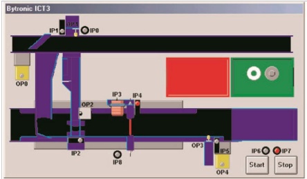
FIG. 8 Industrial Controller Simulation
The Ladsim ICT3 simulation shows the Industrial Controller from above and performs as a slightly simplified representation of it. Rings and pegs are placed onto the chain conveyor from the green source hopper by clicking upon them.
Inputs
Label Name Non-detection status
IP0 Metal Peg Detect Low
IP1 Sort Area Low
IP2 Hopper Full Low
IP3 Ring Assembled High
IP4 Component Detect High
IP5 Reject Area Low
IP6 Start Low
IP7 Stop High
IP8 Belt Peg Detect Low
Outputs
Label Name
OP0 Chain Motor (upper conveyor motor) OP1 Sort Solenoid
OP2 Rotary Solenoid (allow rings into hopper) OP3 Reject Area
OP4 Belt Motor (lower conveyor motor).
When OP0 is on, the rings and pegs will move along the chain conveyor. IP1 detects the presence of any item in the sort area. Simultaneously IP0 detects the presence of a peg. Activating OP1 will push an item in the sort area down the ring chute. Pushing a peg into the chute will jam the system and cause an error. The simulation will then stop and you will be informed of the error. Rings that are not sorted from the chain conveyor continue along and are fed down the end chute onto the belt conveyor where they continue along the conveyor and should eventually be rejected. Rings that are sorted into the ring chute are held in place until OP2, the rotary solenoid, is activated. This loads a single ring into the
hopper, holding any others waiting in the queue. When a ring is indexed into the hopper, IP2 activates to indicate the hopper is now full and the ring is lined up to load onto any peg passing beneath. If the rotary solenoid, OP2, is activated with the hopper already full, the hopper will jam and the simulation will halt. The ring chute can hold five rings in addition to one in the ring hopper; an attempt to push another into the chute will produce a warning that this latest ring will bounce off the waiting stack and continue along the chain conveyor.
OP4 activates the belt conveyor. Pegs on the belt conveyor automatically line up with the ring hopper. The inductive and capacitive sensors IP8 and IP3 simultaneously detect the properties of an item. IP8 detects metal and so is activated by either single pegs or assembled pegs.
IP3 detects the presence of an object adjacent to the sensor and is positioned in such a way that it only detects an assembled ring. Further down the belt, the through-beam sensor IP4 senses any passing item. At the end of the belt IP5 detects any item in the reject area. Activation of OP3 will push any item in the reject area into the red reject bin. A tally of assemblies that have entered the "accept area" and lone rings and pegs pushed into the reject bin should be kept. A complete control program should do the following:
• Use the Start and Stop buttons IP6 and IP7 to activate and deactivate both the chain conveyor OP0, and the belt conveyor OP4.
• Use the Metal Peg Detect IP0 and Sort Area IP1 sensors at the sorting area to determine the identity of the item and by activating the Sort Solenoid OP1, sort the rings into the ring chute. Pegs should be allowed to pass, enabling them to continue down onto the belt conveyor.
• Use a counter to record the number of rings in the chute: when full (5 rings in queue), no further rings should be added.
• Activate the Rotary Solenoid OP2 to dispense rings into the assembly hopper when the Hopper Full sensor IP2 indicates that it is empty.
• Use the Belt Peg Detect sensor IP8 and the Ring Assembled sensor IP3 to determine whether the component is a correctly assembled part.
• Use the Component Detect sensor IP4 as an index to allow for multiple components on the belt conveyor.
• Use the Reject Area sensor IP5 to detect when a part is at the reject area and determine from the data captured previously whether the component needs to be accepted or rejected. Use the Reject Solenoid OP3 to reject bad components off the conveyor.