Calculate the capacitive reactance

Assignment Help Electrical Engineering
Reference no: EM13806208

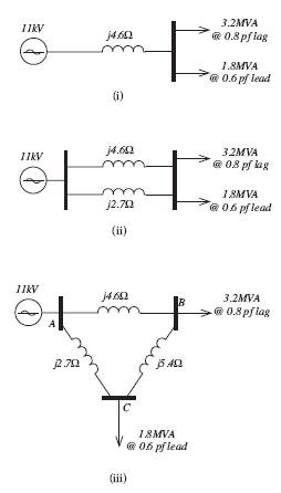
1. For the following distribution feeder systems shown in FIGURES 3(i), (ii) and (iii) determine the load voltage levels.

2040_Determine the load voltage levels.png

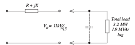
2. The following phase schematic diagram (FIGURE 4) shows an 11 kV, 50 Hz, 3-phase, short line feeding a load. By calculation or constructing the phasor diagram (use a scale of 1 mm = 2 A) for the load cuntnt with VR as reference, determine the capacitive current and
• calculate the capacitive reactance/ph such that the load power factor is increased to 0.98 lag

• calculate the percentage reduction in line current with this value of capacitive reactance in circuit.

647_Determine the load voltage levels1.png

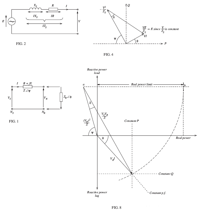
3. (a) A short 3-phase II kV line delivers a load of 4.1 MW, 2.6 MVAr lag. If the series impedance of the line is (72 + j12.1) LI/ph, calculate the sending end voltage and load angle.

(b) Develop the receiving end performance chart for the above line and load to a 3-phase power scale. (Use a scale of 10 mm = 1000 V and 30 nun = 4.1 MW.)

4. Using the chart you produced in Question 3, determine:

(a) the real and reactive power when

(i) the transmission angle remains unaltered and the sending end 'oltage is increased by 28%

(ii) the original sending-end voltage is reduced by 15% and the transmission angle increased by 9°. (Use the same scale as that for Question 3 (b))

(b) the real power limit for the sending voltage in (ii) above (i.e. when reduced by 15%). FIGURE I shows four generators feeding into a sectionalised busbar with a fault limiting reactor.

5. Figure 1 shows four generators feeding into a sectionalised busbar with a fault limiting recactor.

2286_Determine the load voltage levels2.png

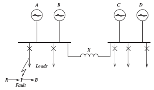
Each generator is rated at II kV and 30 MVA and has a reactance of 02 p.u.

Calculate the value of the reactance to limit the fault level on a feeder to 500 MVA.

6. Compare FIGURES 2 and 4 with those of FIGURES I and 8 and state briefly why they are similar.

2398_Determine the load voltage levels3.png

7. FIGURE 2 shows the sectionalised busbar of a two generator power station connected to the national grid.

1953_Determine the load voltage levels4.png

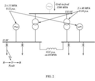
Calculate, using a 40 MVA base, the fault level for a 3•phase symmetrical short circuit on the 11 kV feeder.

8. An 11 kV, single phase system is protected by a scheme using 1000/5 CTs and an IDMT relay having a plug setting of 150% and time multiplier setting of 0.68 (FIGURE 3).

Using the standard PSM/time characteristic, find the relay operating time (TMS = I) for a 236 MVA fault.


932_Determine the load voltage levels5.png

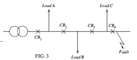
The circuit breakers CB,, CB2, CB3 and CB, are part of a scheme which uses 1000/5 as and IDMT relays.

If the maximum fault current capability is 6700 amps, clearance of which must be initiated in 225 secs, select, using the standard characteristic:

(i) plug setting multipliers for CB, at plug settings of 100% and 50%

(ii) the time multiplier setting of each IDMT relay to afford effective discrimination of 0.4 sec at a plug setting of 50%.

Reference no: EM13806208

Questions Cloud

Write a paper about modern political systems in middle east : Write a paper about modern political systems in the Middle East since the end of World War I until the so called Arab Spring.
The profit-maximizing level of output : What is the profit-maximizing level of output? How much profit does the firm make? Should it produce this output or shut down?
What is the goal of your website : What is the goal of your website? What do you want people to learn, believe, or do after interacting with your website? Is your purpose narrow and specific enough that you can adequately achieve it in a small- scale project
When a sales force is organized by product lines : When a sales force is organized by product lines
Calculate the capacitive reactance : Calculate the capacitive reactance/ph such that the load power factor is increased to 0.98 lag and calculate the percentage reduction in line current with this value of capacitive reactance in circuit.
Describe six components of the organization : Choose an organization delivering goods and/or services globally. Provide a background of the organization and fully describe six components of the organization's supply chain. Examine the potential problems related to each of the components descri..
Process design matrix : Write an executive summary identifying appropriate design approaches for a selected product and service.
Explain what given quote means and how it applies to life : Explain what the following quote means and how it applies to your life
Describe the properties and usage of digital signatures : Describe the properties and usage of digital signatures. Evaluate digital signatures based on their legal ability to stand up in court

Reviews

Write a Review

Electrical Engineering Questions & Answers

  Lithium ion battery technology

The paper includes Lithium ion battery technology with its advantages and disadvantages. The paper discusses about the Lithium air battery in which detailed reactions of Lithium with air including nonaqueous as well as aqueous are given.

  Power transformers and tariffs

Construction of different types of power transformer, significant energy savings

  Paper on orthogonal frequency-division multiplexing

This document is shown a paper on Orthogonal frequency-division multiplexing with advantages, disadvantages and uses.

  Function of the hmi in a scada system

This assignment contains electronics engineering questions like State the commonly found components of a SCADA (Supervisory control and data acquisition) system. and decribe the function of the HMI in a SCADA system.

  Resultant waveform of the odd harmonic series

Prepare an Excel graph showing the individual components and summated resultant waveform of the odd harmonic series resulting in an approximate square wave.

  Explain scada system

Explain the function of the HMI in a SCADA system.

  Design a 2-digit 24 second shot-clock

Design a 2-digit 24 second "shot-clock" countdown timer with pushbutton controller.

  Model a discrete-time system

To understand di erent signal models To be able to model a discrete-time system and design simple signal processing algorithms.

  Draw a relay construction diagram

Draw a relay construction diagram and briefly explain the operation of a relay.

  Frequency division multiplexing

Write a short technical report on Frequency Division Multiplexing

  Impact of electron energy

Briefly discuss the impact of electron energy, electron current and target on the Bremsstrahlung generated.

  Traffic light controller

The schematic of the traffic light controller

Free Assignment Quote

Assured A++ Grade

Get guaranteed satisfaction & time on delivery in every assignment order you paid with us! We ensure premium quality solution document along with free turntin report!

All rights reserved! Copyrights ©2019-2020 ExpertsMind IT Educational Pvt Ltd