Reference no: EM132524825
EN7908 Manufacturing, Control and Environmental Sustainability - Bahrain Polytechnic
Learning outcome 1: Critically analyse the effectiveness of a feedback control system for a practical engineering application.
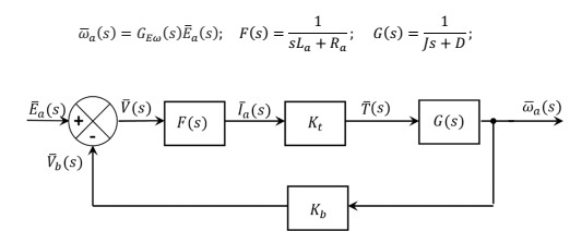
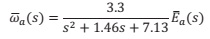
Task 1) The block diagram depicting the vertical casting process described above is shown in figure Q1. By solving sub-question a) to d), simplify the block diagram to show that the closed loop transfer function between the input signal E¯a(s) and the output signal ω¯a(s) is
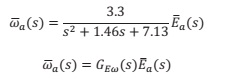
ω¯a(s) = 3.3/(s2 + 1.46s + 7.13).E¯a(s)
where
a) Simplify the forward path of the block diagram to show that the transfer function between ω¯a(s) and V¯(s) is
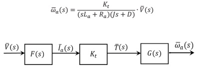
ω¯a(s) = kt/(sLa + Ra)(Js + D).Vs
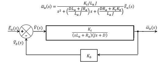
b) Using the shortcut rule show that the closed loop transfer function between E¯a(s) and ω¯a(s) is
c) Define the following quantities in MATLAB
• Da = 0.02 and DL = 2 N-m-s/rad (newton-meters- seconds/radian).
• Ja = 6 × 10⁻⁴ and JL = 6 kg-m2 (kilograms-meters2).
• N1 = 100; N2 = 1000
• Kt = 2; Ra = 8Ω; Kb = 2 volts, La = 10 mH
and calculate the parameters J and D using the following relations
J = Ja + JL (N1/N2)2; and D = Da + DL (N1/N2)2
d) By using appropriate MATLAB commands, show that the closed loop transfer function between the input signal E¯a(s) and the output signal ω¯a(s) is
Q2) By equating the standard second order transfer function to GEω(s), calculate the following analytically
a) Undamped natural frequency ω?? .
b) Damping ratio ??.
c) Steady state gain.
d) Steady State output to a unit step.
Q3) Verify the stability of the system by carrying out the following
a) Write down the denominator equation of the transfer function and set it to zero.
b) Calculate analytically the poles of the transfer function
c) Verify the result in b) using an appropriate MATLAB command.
d) Verify using MATLAB the stability of the system by graphically computing the poles of the system.
Q4) Evaluate the impulse response of ωa(t), where
a) By substituting a unit impulse signal for the input E¯a(s) and by completing the square, write down the signal ω¯a(s).
b) Using inverse Laplace transforms, evaluate the impulse response ωa(t).
c) Using the MATLAB impulse function, produce a unit impulse response for the output ωa(t),
d) Using MATLAB, verify the result in c) by plotting it with the analytical result derived in b). Select the time scales so that both the transients and the steady state regions are visible.
Q5) Consider the following feedback loop arrangement outlined in Figure Q5. Assume that disturbances d¯(s) enter the system as shown in the diagram. It is assumed that the reference input ??¯(s) is normally held constant, and the response characteristics to disturbances are a very important consideration for the casting process. A PID controller is placed at the forward path
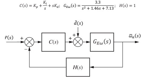
a) In the absence of the reference input, i.e. ??¯(s) = 0, analytically derive the closed-loop transfer function between ω¯a(s) and d¯(s).
b) The performance specification for the closed loop system requires that the unit step disturbance response be such that the settling time to be 1 to 2 seconds and the system's transient response has reasonable damping. We may interpret the specification as ?? = 0.8 and ω?? = 4 rads/sec for the dominant closed-loop poles. We may choose the third pole at s = - 10 so that the effect of this real pole on the response will be negligible.
Derive the required closed loop characteristic polynomial that satisfies the above performance specification.
c) Design a Proportional Integral Derivative Controller (PID) that satisfies the requirements in b).
d) Assuming a unit step disturbance, show analytically that the steady state output due to a disturbance of the closed loop system with the PID controller is zero. Demonstrate this with an appropriate time response plot using MATLAB. What are the implications of the integrator placement on either GEω(s) or C(s) on the steady state error due to a disturbance?
Attachment:- Control Project Casting.rar