Reference no: EM132390049
BPE3513 Computer Aided Design
Assignment Title: Basic Part Modelling
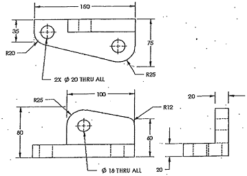
INSTRUCTION - Use the following graphics with the design intent to create the part.
1. Insert fillet at edge of the part marked with red dashed line.
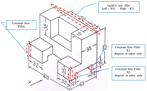
2. Given:
1. Holes are concentric to circular edges created by fillets and rounds.
2. Thickness of bosses are equal.
3. All holes are through holes
Requirements:
Use the following function to create the part; Boss Feature, Hole Wizard and Fillet.
Prepare a report in word file consists of the following items: -
- Part Sheet with FeatureManager Design Tree displayed.
- Drawing Sheet (related views) with actual measurement (tangent edge removal and show the hidden line).
- Detail step by step procedures taken by yourself to create the part.
You are required to produce two outputs from this assignment.
Output 1 - Printed Report
1. This report should consist of the following items:
a) The print screen of solidworks part sheet
b) Detail step by step procedures to create the part
2. Print the report (2 sided) without colour.
3. Submit in my pigeon hole Output 2 - Solidworks drawing File
1. Produce solidworks drawing File for part in Q1 and Q2.
2. This Solidworks drawing file should consist of:
a. Related drawing views
b. Part's actual measurement (tangent edge removal and show the hidden line).
Attachment:- Computer Aided Design Assignment File.rar