Assume that capacitor is completely discharged when tlt0

Assignment Help Electrical Engineering
Reference no: EM13371629

Assume that capacitor is completely discharged when t<0. Plot these graphs in MATLAB or any other computing software that you are comfortable with.

For the RC circuit in the figure:
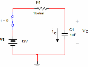
1384_calculate the expression for the voltage and current.png

1)  Hand calculate the expression for the voltage and current of the capacitor and plot these equations by using MATLAB.

2)  Plot the capacitor voltage and current for R=200Ohm and C=1µF, R=5k and C=700mF and comment about the differences you see in the graphs.

3)  Calculate the time constants of each circuit and point out this time constants at your voltage graphs.

4)  Hand calculate the expression for the voltage and current of the resistor and plot these equations by using MATLAB.

5)  Assume the output is taken from the capacitor in this RC system with R=200Ohm and C=1µF.

Plot the step and impulse response of the system by using the LSIM (you can use TF function before LSIM to calculate your system coefficients)  function of MATLAB.

6)  Assume the output is taken from the capacitor in this RC system with R=200Ohm and C=1µF. This RC system is a first order low pass filter with a break frequency. Calculate the break frequency for this system.

7)  Apply two ac signals (x1(t) and x2(t))to your system by using LSIM function of MATLAB.

X1(t) is a sinusoidal signal with 500 Hz frequency and x2(t) is a sinusoidal signal with 100 Hz frequency. You will notice different effects of your RC system (low pass filter)  to these signals. What is the reason for this difference.

Reference no: EM13371629

Questions Cloud

Ethics morality and leadership the awb scandalthe series of : ethics morality and leadership the awb scandalthe series of corporate scandals and transgressions that have emerged
1 what does an instructional designer know2 according to : 1. what does an instructional designer know?2. according to reiser what is the ?eld of instructional technology?3. what
1 construct an explicit deformation retraction of the torus : 1. construct an explicit deformation retraction of the torus with one point deleted onto a graph consisting of two
Part-11theory of the firmaif in an efficient brewing : part-11.theory of the firmaif in an efficient brewing industry firms operating at lowest possible average cost produce
Assume that capacitor is completely discharged when tlt0 : assume that capacitor is completely discharged when tlt0. plot these graphs in matlab or any other computing software
Course description a development of value and distribution : course description a development of value and distribution theories. detailed analysis of the reactions of consuming
The fourier transform is a powerful tool for converting : the fourier transform is a powerful tool for converting time-series data into its frequency components for the purpose
Task 1 fill out surveyplease take the 122223 survey at : task 1 fill out surveyplease take the 122223 survey at survey.osble.orgindex.php?sid97282. please treat the question
Bt co a beverage manufacturer manufactures one product - : bt co a beverage manufacturer manufactures one product - trublood. bt accounts for its finished goods inventory using

Reviews

Write a Review

Electrical Engineering Questions & Answers

  Determine how much does the sphere holding q2 weight

two charges of equal sign and magnitude are placed on metal conducting spheres. charge q1 is fixed, while the sphere holding q2 is suspended by a thread from point A.if q1 = q2 =1 µC and θ = 40"

  Design a negative edge-triggered d flip-flop that uses

design a negative edge-triggered d flip-flop that uses three sr latches constructed with cross-coupled nor gates.

  Design a logic circuits that will produce high output

a 4 bit binary number is represented as A3,A2,A1,A0 whereA3,A2,A1 and A0 represent the individual bits where A0 is LSB. design a logic circuits that will produce HIGH output whenever the three binary number is greater than 0010

  Derive the state diagram-state table and a suitable circuit

A sequential circuit hast two inputs (w1 and w2) and one output (z). Its function is to compare the input sequences on the two inputs. If w1 = w2 during any four consecutive clock cycles, the circuit produces a z=1; otherwise, z=0.

  Find the voltage-current relation for time varying capacitor

A time -varying capacitor is characterized by the charge-voltage equation. That is, the capacitance is not a constant but a function of time. Given that i(t) =dq(t)/dt, find the voltage-current relation for this time varying capacitor.

  What is the load resistance in ohms as measured

A 5-MVA, 66:13.2kV, three-phase transformer supplies a three-phase resistive load of 4,500kW at 13.2kV. What is the load resistance in ohms as measured from the line-to-neutral on the high-voltage side of the transformer, if it is connected in Y-Y..

  Calculate the rated primary and secondary currents

Calculate: a. The rated primary and secondary currents b. The secondary voltage if it is connected at full load of 2000 kW c. The voltage regulation from no-load to full load. Voltage regulation is given by: (E(no-load)-E (full-load))/E(full-load)..

  A manufacturer specification sheet lists the transfer

a manufacturer specification sheet lists the transfer function of a pressure sensor as 45plusmn5 mvkpa with a time

  What was the actual achieved issue rate of instructions

It has a clock speed of 3.2Ghz. It executes a program with 1.8 billion instructions in 1.4 seconds, devoting 90% of the CPU's time to the program. What was the actual achieved issue rate of instructions per cycle

  Find the no load speed-stalled torque and stalled current

The resistance of the coil is 0.2 ohm. The inductance of the coil is 1.2e-4 H. The rotor inertia is 1.0e-5 kg m2. The current to torque gain is 0.03 Nm/A. The friction torque is 0.09 Nm. A 12 V voltage source is applied to the motor.

  Determine the time taken to execute the first instruction i1

A chip design company comes up with a new 4-stage pipelined design to execute instructions such that stage s1 takes 30 ns, s2 takes 30 ns, s3 takes 50 ns and s4 takes 30 ns of processing time.

  Determine difference equation by pole-zero placement method

A first order highpass filter is required to satisfy the following specifaction fs=10000Hz fc=4000Hz Find the transfer function and difference equation by the pole-zero placement method.

Free Assignment Quote

Assured A++ Grade

Get guaranteed satisfaction & time on delivery in every assignment order you paid with us! We ensure premium quality solution document along with free turntin report!

All rights reserved! Copyrights ©2019-2020 ExpertsMind IT Educational Pvt Ltd