Reference no: EM132234791
Assessment - IP routing
Part A: Implement IP routing in a simulated environment Scenario
‘Effective Design' (ED) is a software solutions provider located in Melbourne. They are planning to have three more branches in Perth, Queensland and Sydney.
Before moving to the actual design and implementation phase ED want one of their IT staff members to come up with a simulated design of the proposed network.
ED's Network Manager has already come up with the topology and the IP addressing scheme for the topology. Below as shown in Figure 1 is the topology proposed by the Network Manager.
Figure 1
Details of the proposed topology are as follows:
- There are 4 routers (Cisco 2811), one for each branch. HQ-Melbourne is the edge router for the Melbourne branch. B-Perth is the edge router for Perth branch. B-Queensland is the edge router for Queensland branch. B-Sydney is the edge router for Sydney branch.
- Altogether, there are four Local Area Networks (LANs) and three Wide Area Networks (WANs).
- Melbourne LAN is connected to the HQ-Melbourne router.
- Queensland LAN is connected to the B-Queensland router.
- Sydney LAN is connected to the B-Sydney router.
- Perth LAN is connected to the B-Perth router.
- The network address of each subnet is already decided. Table 1 shows the list of network names and the planned network addresses.
|
Network
|
Network address
|
|
|
|
|
Melbourne LAN
|
172.16.10.0/28
|
|
|
|
|
Queensland LAN
|
172.16.10.16/28
|
|
|
|
|
Sydney LAN
|
172.16.10.32/28
|
|
|
|
|
Perth LAN
|
172.16.10.48/28
|
|
|
|
|
Mel_to_Queens WAN
|
195.168.50.0/30
|
|
|
|
|
Mel_to_Sydney WAN
|
195.168.50.4/30
|
|
|
|
|
Mel_to_Perth WAN
|
195.168.50.8/30
|
|
|
|
|
|
|
Table 1
Requirement
You have been approached by ED's IT Manager to implement, configure and troubleshoot the proposed network in a simulated environment and ensure that it is ready for actual implementation.
Task 1: Building the topology
Create the network diagram shown in Figure 1 using Cisco packet tracer. Use suitable cable types when cabling the devices. Label the devices as depicted in Figure 1.
a) Save the Cisco Packet Tracer file as xxx_cse2cnx_assessment3.pkt. (where xxx is your student number)
b) Include a screenshot of your topology as evidence of the completion of this task.
Task 2: Planning IP addresses
The allocated network addresses are given in Table 1. Refer Table 1 before starting this task.
Guidelines for planning:
- The default gateway for each LAN should be the last useable IP address of the subnet.
- All end device IP addresses can be assigned using any useable IP address from the useable range for that subnet.
Fill the attached Table 2 with your planned IP addresses and default gateways.
Task 3: Configuring ethernet and Serial interfaces
a) Configure ethernet interfaces of all the end devices (M-PC1, M-PC2, Q-PC1, Q-PC2, S-PC1, S-PC2, P-PC1, P-PC2) with the IP addresses, subnet masks and default gateways from Table 2.
For M-PC1, Q-PC1, S-PC1 and P-PC1 take screenshots of the completed IP configuration window as evidence of the completion of this task and include in the word file.
b) Configure and activate ethernet and serial interfaces on each router using IP addresses and subnet masks from Table 2.
c) Issue the command "show ip interface brief" on each router and provide screenshots of the output.
Task 4: Basic configuration of the routers
a) Configure the following on HQ-Melbourne, B-Queensland, B-Sydney, B-Perth.
- Configure the router hostname as depicted in Figure 1 (labels).
- Configure an enable password.
- Configure an enable secret.
- Configure a console password.
- Configure a telnet password.
- Configure the ‘Message of the Day' banner (MOTD) as "Unauthorized access is prohibited!!".
- Save the configurations.
b) Fill Table 3 as shown below with the chosen hostnames and passwords for each of the routers. Name the tables as Table HQ-Melbourne, Table B-Queensland, Table B-Sydney and Table B-Perth.
c) Take a screenshot of the startup-configuration of each router and include in the Word file as evidence of completing this task.
Task 5: Configure OSPFv2 on routers
a) Configure OSPF on router, HQ-Melbourne. Table 4 shows a breakdown of the configuration tasks. Issue "show ip protocols" command on the HQ-Melbourne router and provide a screenshot of the output.
b) Configure OSPF on router, B-Queensland. Table 5 shows a breakdown of the configuration tasks. Issue "show ip protocols" command on the B-Queensland router and provide a screenshot of the output.
c) Configure OSPF on router, B-Sydney. Table 6 shows a breakdown of the configuration tasks. Issue "show ip protocols" command on the B-Sydney router and provide a screenshot of the output.
d) Configure OSPF on router, B-Perth. Table 7 shows a breakdown of the configuration tasks. Issue "show ip protocols" command on the B-Perth router and provide a screenshot of the output.
Task 6: Verifying the OSPFv2 configurations
a) Which command will list all connected neighbours and the adjacency state?
b) Issue the command that lists all connected neighbours on each router and provide screenshots of the output.
c) Which command will display the IP routing table of a router?
d) Provide screenshots of each routers' routing table.
Task 7: Verify network connectivity
a) Issue the "ping" command from M-PC1 to Q-PC1. Include a screenshot of the ping command output.
b) Issue the "ping" command from M-PC1 to S-PC1. Include a screenshot of the ping command output.
c) Issue the "ping" command from M-PC1 to P-PC1. Include a screenshot of the ping command output.
Part B: Apply routing algorithms
Requirement
You are asked to use two different routing algorithms to find the shortest paths in a network.
These are as follows.
• Dijkstra algorithm
• Bellman Ford algorithm
The network topology with all the link costs is shown below in Figure 2.
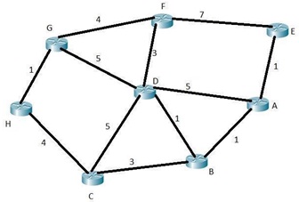
Figure 2
Task 1: Application of Dijkstra's algorithm
Using Dijkstra's algorithm on Figure 2, determine the shortest paths from A to all network nodes.
Part of the answer is given in Table 8. Fill in the blanks (highlighted) in Table 8.
Notes on the table:
• T - Set of nodes so far incorporated by the algorithm
• L(n) - Cost of the least-cost path from source A to node n that is currently known to the algorithm (n is B, C, D, E, F, G and H)
Task 2: Application of Bellman Ford algorithm
Use Bellman Ford algorithm on Figure 2, determine the shortest paths from A to all network nodes. Part of the answer is given in Table 9. Fill in the blanks (highlighted) in Table 9(attached).
In the table:
• h - Maximum number of links in path at current stage of the algorithm
• Lh(n) - Cost of the least-cost path from source A to node n under constraint of no more than h links (n is B, C, D, E, F, G and H)
Attachment:- Assessment - IP routing.rar