Reference no: EM132828769
FEA Applications Task
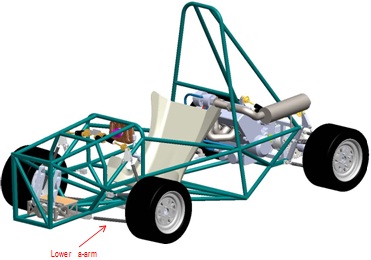
Analysis of a suspension lower front a-arm for cornering and braking loads
Steps:
1. Download the provided parasolid file (LowerArmIncSpherical) and import to SpaceClaim
2. In SpaceClaim draw a pin and which restricts the motion of the outboard rose joint (a.k.a rod end) as shown below:
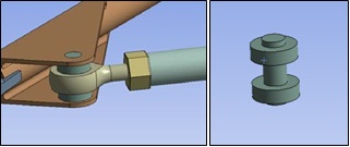
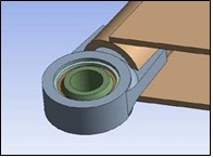
3. Add a retaining ring (see teal coloured ring in image below) to hold the spherical bearing to the bearing retainer. Set the inside diameter of the retaining ring to 17 mm.
4. Exit SpaceClaim and load the model. Set all contacts to bonded except for:
a. Between the pin you just added and the outboard rose joint. Set this to frictionless.
b. The contact between the spherical ball (green in above image) and bearing cup (orange in above) to no separation. This is similar to frictionless, but will not allow for separation under load. This may not be 100% realistic, but we are analysing the arm, not the bearing and it will assist Ansys's solver and will still allow the ball to articulate (unlike bonded)
c. Between the retaining ring you added and the bearing cup. Set this to no separation to allow for sliding between the bearing retainer and bearing cup.
d. Set the contact between the bearing retainer (grey-blue above) and retainer cup to no separation. Ideally this should be frictionless to allow for deformation of the retaining cup; however, this makes the analysis nonlinear and complex for Ansys to solve
5. Develop an initial mesh (this can be refined once you know the model is working).
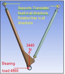
6. Add the following loads and supports. Add the bearing load to the internal face (i.e. bolt hole) in the spherical ball. For the inboard rod ends explore using remote displacement supports vs using joints connections.
7. Solve the total displacement and equivalent stress in the beam. Note: you may need to add additional supports to avoid rigid body motion, be careful that these supports do not adversely impact your results.
Consider that the spherical ball is connected through the suspension upright to the wheel, so will it be allowed to move in the vertical?
8. Solve the reactions at the supports
9. Improve your mesh using a medium relevance centre for the global mesh. Add a body sizing of 2 mm to the tubular members
10. Re-evaluate the results
Go further...
The pin we added in step 2 does not allow for free rotational movement of the outboard rod end. In reality, rod ends do allow for this. Think about how this may be modelled better.
Submission: Submit a 2 page document showing your configuration in Ansys (inc. the tree). Outline any areas of the mesh that can be improved.
Attachment:- FEA Applications Task.rar