Reference no: EM132674777
LO 1 Apply an understanding of fundamental electrical quantities to analyse circuits with constant voltages and currents
LO 2 Analyse simple circuits with sinusoidal voltages and currents
Assessment brief:
The purpose of this assessment is to provide a framework where the learner is:
1. Able to apply an understanding of fundamental electrical quantities to analyse constant voltages and currents and sinusoidal voltages and currents circuits.
Scenario:
You have recently employed in a firm as technician to do analysis of circuits with direct current and alternating current. The nature of job demands your good knowledge on circuit theory and their applying skill on complex circuits explaining its operation. The tasks are explained in PART 1 and PART B respectively.
PART 1
The task is to analyse model of a car internal lighting circuit -planer circuit showing resistances on different branches. A range of circuits and combination is given, analyze for the parameters to find the wattage of these resistive filament lamps by applying circuit theory and explain the operation of the circuits and evaluate them.
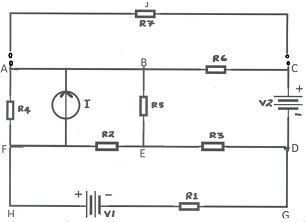
Figure 1: Car lighting model circuit diagram
The details of the resistive filament lamps used in the branches of lighting circuit is given below in table 1. The circuit is for model purpose and lamps total resistance given in the table indicated
45510as a single resistor denoted in planer circuit.
|
Branch Labeled
|
Area
|
Names of the Lamps Fitted in mentioned branch
|
|
A-B-C
|
Front side
|
parking turn, low beam headlamps
|
|
D-E-F
|
Rear side
|
parking, turn, fog, boot, park reverse parking, number plate
|
|
B-E
|
Internal
|
Instrument panel, seat belt lamp, internal lights
|
|
G-H
|
|
Rear window Defroster grid-R1
|
|
C-J-A
|
Head Lamps
|
Additional circuit for high beam head lamps-R7
|
Table: 1 -Car lighting circuit details
Task 1: This task provides evidence
Apply principles of circuit theory to analyse circuits with constant voltages and currents
With reference to the scenario brief above you should apply circuit theory to analyse the given car lighting circuit, for the current through and voltage across each resistive filament lamps to determine the wattage and energy calculation.
To complete this task, the following should be undertaken:
• Analyse the part of simple circuit loop labelled as ABCDEFA for the currents by applying any Kirchhoff's theorems and explain the operation of the circuit.
• Analyse the circuit ABCDGHFA by applying Kirchhoff's mesh analysis for the currents, voltage and energy consumed in the grid resistor R1, if the rear window defroster grid switched on for 10 minutes,
• Analyse the complex circuit when loop extended and added C-J-A loop to ABCDGHA, by applying Thevenin's theorem and Maximum power transfer theorem obtain value of R7 (high beam head lamp) and wattage for maximum brilliance and explain the operation of the whole circuit with explaining and evaluating the operation of circuit with any simulation result.
Guidance/notes to trainees
• Carefully read Scenario brief.
• Apply appropriate circuit theorem for the labelled part of complex diagram given.
• Do the calculation and find the parameters as asked in the task.
• Explain and evaluate the circuit operation mentioning the current, voltage, wattage and energy calculation according to the given task.
• Use scientific calculator, Cramer's rule and show sequential steps of solution.
• Use Proteus or any simulation software for evaluation of your analysis.
Evidence for this Task
• Please be guided by the assessment criteria and task accordingly submit evidence.
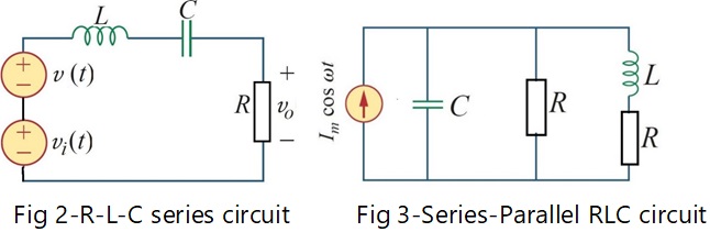
Part B Analyse the following filter circuit applications of series and series-parallel RLC sinusoidal circuits.
Task 2: This task provides evidence for LO:2 (P2,M2 & D2)
Refer to given scenario and range of circuit diagrams given in figure 2 and 3 :
• Analyse the Fig 2 RLC series circuit sinusoid to calculate the steady state output voltage and current.
• Analyse for the steady state expressions for the currents flowing through L-R branch of fig 3-Series parallel circuit.
• Analyse the both filter circuits above for the resonance condition and understand the operation of the circuit by plotting necessary frequency response or reactance/angular frequency graph.
Guidance/notes to trainees
• Analysis of the diagram circuits given in figure 2 & 3 by complex number calculation to find the steady state expressions for the circuits and operation including resonance condition
Evidence for this Task
Please be guided by the assessment criteria and task accordingly submit evidence
Attachment:- Fundamental electrical quantities.rar