Reference no: EM132733275
6MA041 Supersonic and Subsonic Aerodynamic - University of Wolverhampton
LO 1 Demonstrate a comprehensive understanding of key aerodynamic principles and their interaction with related engineering disciplines such as automotive and aerospace
LO2 Develop an understanding of the capability, scope and limitations of the different mathematical, experimental and computational tools that can be used in the aerodynamic field
LO 3 Use fundamental mathematical, experimental and CFD methods to undertake aerodynamic design and analysis of key engineering structures.
LO 4 Conduct appropriate research and investigations to generate innovative aerodynamic design for engineering vehicle and mechanical components with improved aerodynamic efficiency.
Task 1: Internal flow in a nozzle
A conical diffuser shown in figure 1 has entry and exit areas A I and A2 of 0.01768 m2 and 0.07070 m2 respectively. The total length of the diffuser is 1000 mm and the thickness is 2 mm. The pressure and temperature of air at entry are 1.01390 bar and 295 K. The environmental pressure and the thermodynamics properties for pressure and temperature as 1.01325 bar and 293.2 K respectively.
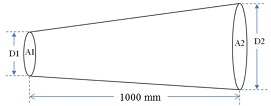
Figure 1: Conical Diffuser
a. Determine the value of the diameters DI and D2 in mm based on the areas given [3 %] in the question. The value of the diameters should be rounded to four decimal places.
b. Using the flow simulation tool in SOLIDWORKS, create 3D - CFD model for [10 %] the flow inside the diffuser using appropriate mesh size.
c. Discuss how the pressure, velocity, and density change inside the diffuser with [10 Vo] the aid of appropriate 2D contours plots and graphs.
d. Assuming that the outlet parameters remain constant and by using the CFD [12 Vo] model, investigate and discuss the trends of the outlet velocity due to the variation of the inlet pressure. Support your discussion with suitable plots and graphs.
e. Validate the results from the CFD model by conducting suitable mathematical 15 %1
calculations and discuss your observations.
Task 2: External flow around a wing
A model wing that can be used for aerospace applications is placed in a test section of a wind tunnel where the pressure, temperature and Mach number of the flow are 1.03 bar, 300 K, and 0.11, respectively. The wing has NACA 0015 aerofoil and a chord length of 61.5 mm. The size of the computational domain is shown in Figure Q2 and the coordinates of the aerofoil surface are provided in Tablel.
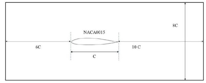
a. Using ANSYS-FLUENT, create a 2D - CFD model of the flow around the [15 %] aerofoil when the wing is at 4° angle of attack. Use Spalart-Allmaras viscous model for the flow. Detail all the steps taken to create this model including geometry, mesh, solver set-up, and so on.
b. Use the CFD model to determine the drag and lift coefficients (CD and CO of the [15 %] aerofoil at two different angles of attack including 4° and 12°. Discuss critically the influence of angle of attack on the lift and drag coefficients and overall aerodynamic behaviour of the wing. Support your discussions with suitable plots and graphs.
c. Compare the results of the CFD model with reliable aerofoil data available either in [10 %] aerodynamic textbooks or research papers. Discuss whether the created CFD model is valid for this particular analysis and provide suggestions to improve its predictions.
d. Assuming the wing is placed at 4° angle of attack; create CFD models for the flow [20 %] around the aerofoil at two different values of Mach numbers including 0.6 and 1.2. Use appropriate plots and parameters to discuss the influence of Mach number on the aerodynamic behaviour of the wing and the flow pattern around it.