Reference no: EM133039842
21003K Engineering Science - Bahrain Training Institute
Assignment - DC and AC circuits
Learning Outcome 1: Determine parameters within mechanical engineering systems
Purpose of this assignment
The assignment is designed to assess the student's ability to analyse circuits working on both direct and alternate currents.
Scenario
Imagine yourself to be a senior technician at an electrical company out for a routine test of some basic places. There would be places and components across which you may need to calculate the current through and voltage across, both in dc and ac circuits. As you know, you would need to use circuit laws and theorems to do so. You would also need to do so in circuits which are not simple - but are combined in series and parallel. Occasionally, you'd need to analyse the outcome of two or more ac currents when they mix sinusoidally. You may need to analyse generators and transformers according to the principles of electromagnetic induction. The current assignment assesses your skill in all these domains.
Part 1
(i) Use the superposition theorem to calculate,
(a) the current i,
(b) and the voltage v in the DC circuit across the E k? resistor as shown in Figure 1 below.
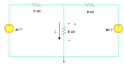
Figure 1
Part 2
2. (i) For the series RLC ac circuit shown in Figure 2 below, calculate the current through the circuit and the voltage across the inductor. Give your answers in both the time and frequency domains.
(ii) For the series RLC circuit shown below in Figure 3, determine the voltage across the capacitor in the time domain.
Part 2
2. (i) For the series RLC ac circuit shown in Figure 2 below, calculate the current through the circuit and the voltage across the inductor. Give your answers in both the time and frequency domains.
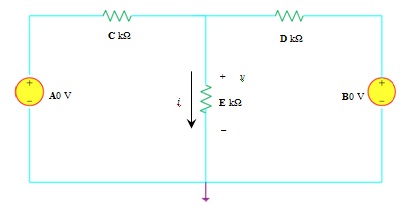
Figure 2
(ii) For the series RLC circuit shown below in Figure 3, determine the voltage across the capacitor in the time domain.
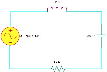
Figure 3
Guidance/notes to trainees
Use ideas of series ac circuits.
Evidence for this task
Show all your work and calculations.
Refer to problem (3) above. The voltage we obtained across the capacitor was of the form v_C=A cos??(B? t+C)+D cos?( Et+F). Use the numbers from A to F as assignned by your instructor andplot the complex waveform and describe how it was produced by combining the two sinosoidal waveforms. Include as part of your description, the following :
(a) the harmonics and fundamental, if any,
(b) the amplitude of the harmonics,
(c) the (angular) frequency of the harmonics,
(d) the time period of the harmonics,
(e) phase of the harmonics,
Guidance/notes to trainees
Use ideas of ac sinusoidal waves and harmonics.
Evidence for this task
Show all your work and calculations.
Refer to the problem (3) above. A capacitor is addedas shown in Figure 4 below between the branches and a small change is made to the second AC voltage source so that both sources have the same frequency. A newcombined series-parallel RLC circuit is provided.
(i) Calculate the current through the new capacitor using the two techniques of your choice.
(ii) Evaluatethe techniques used by commenting briefly as to which of them was easier to solve the given problem with justification.
Guidance/notes to trainees
Use ideas of ac circuits, Kirchhoff's laws, Superposition, Thevenin's and Norton's theorems, according to your choice.
Evidence for this task
Show all your work and calculations.
Refer to problem (3) above. The voltage we obtained across the capacitor was of the form v_C=A cos??(B? t+C)+D cos?( Et+F). Use the numbers from A to F as assignned by your instructor andplot the complex waveform and describe how it was produced by combining the two sinosoidal waveforms. Include as part of your description, the following :
(a) the harmonics and fundamental, if any,
(b) the amplitude of the harmonics,
(c) the (angular) frequency of the harmonics,
(d) the time period of the harmonics,
(e) phase of the harmonics,
4. Refer to the problem (3) above. A capacitor is addedas shown in Figure 4 below between the branches and a small change is made to the second AC voltage source so that both sources have the same frequency. A newcombined series-parallel RLC circuit is provided.
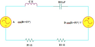
Figure 4
(i) Calculate the current through the new capacitor using the two techniques of your choice.
(ii) Evaluate the techniques used by commenting briefly as to which of them was easier to solve the given problem with justification.
Part 3
5. (i) Refer to Figure 2 in Problem (3) above. An inductor is added in the vicinity of the inductor present as shown in Figure 5. The following questions are in reference to the principles of electromagnetic induction :
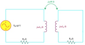
Figure 5
(a) Describe with explanation what happens in the second coil when the given ac source is switched on in the first coil.
(b) Describe with explanation what will happen in the second coil when the ac source is replaced by a dc source and it is switched on.
(c) If in question (b), we changed the value of the dc voltage from lower to higher, describe with explanation what will happen in the second coil.
(ii) The following questions refer to the applications of electromagnetic induction :
(a) For the coil of an ac generator, explain the factors that influence the ac current generated by the coil.
(b) Assume the coil of the ac generator starts with its axis perpendicular to the magnetic field (0o) . Describe with explanation the amounts and directions of the induced current as the coil rotates through a complete cycle.
(c) For an ideal transformer, explain how the secondary voltage and current depend on the voltage, current and the number of turns in the primary circuit.
Attachment:- Engineering Science.rar