How Wien Bridge Oscillator Works:
Figure 1, shows a Wien Bridge oscillator. The operational amplifier is used in the non-inverting configuration, and the lead-lag network provides feedback. Resistors Rf and R1 determine the amplifier gain and are selected to make loop gain equal to 1. If the feedback circuit parameters are selected properly, there will be some frequency at which there is zero phase shift in signal fed back to non inverting terminal. Because amplifier is non inverting, it contributes zero phase shift, so the total phase shift around loop is 0 at that frequency, as required for the oscillation.
The oscillator uses the positive and negative feedback. The positive feedback helps oscillations to build up when the power is turn on. After output signal reaches the desired level negative feedback reduces the loop gain is 1. The positive feedback is through the lead lag network to non-inverting input. The negative feedback is through the voltage divider to inverting input.
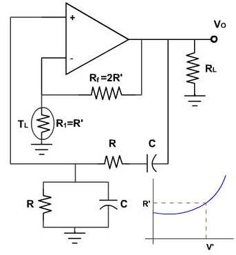
Figure 1
At power up, tungsten lamp has a low resistance, and thus, negative feedback is less. For this, reason, loop gain AB is greater than 1, and oscillations can build up at the resonant frequency fr. As oscillations build up, the tungsten lamp heats up a little and its resistance increases. At the desired output level tungsten lamp has a resistance R'. At this point
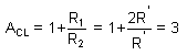
Since the lead lag network has a gain (=B) of 1/3, loop gain AB equals unity and then the output amplitude levels off and becomes constant. The frequency of the oscillation can be adjusted by selecting R and C as

The amplifier should have a closed loop cut off frequency above the resonant frequency, fr.
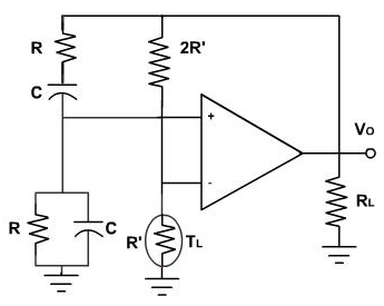
Figure 2
Figure 2, shows another way to represent the Wein Bridge oscillator. The lead lag network is the left side of bridge and voltage divider is the right side. This AC Bridge is called as Wein Bridge. The error voltage is output of the Wein Bridge. At the time when bridge approaches balance, the error voltage approaches zero.
Email based Electronics Devices and circuits assignment help - homework help at Expertsmind
Are you searching Electronics Engineering assignment help expert for help with Wien Bridge Oscillator Working questions? Wien Bridge Oscillator Working topic is not easier to learn without any external help? We at www.expertsmind.com offers free lecture notes for Electronics Devices and circuits assignment help and Electronics Devices and circuits homework help. Live tutors are available 24x7 hours for helping students in their Wien Bridge Oscillator Working related problems. We provide step by step Wien Bridge Oscillator Working question's answers with 100% plagiarism free content. We prepare quality content and notes for Wien Bridge Oscillator Working topic under Electronics Devices and circuits theory and study material. These are avail for subscribed users and they can get advantages anytime.
Why Expertsmind for assignment help
- Higher degree holder and experienced experts network
- Punctuality and responsibility of work
- Quality solution with 100% plagiarism free answers
- Time on Delivery
- Privacy of information and details
- Excellence in solving electronics engineering questions in excels and word format.
- Best tutoring assistance 24x7 hours