Uni-junction transistor
UJT Relaxation Oscillator:
The characteristic of UJT was discussed in earlier. It is has negative resistance region. The negative dynamic resistance region of UJT can be taken in use to realize an oscillator.
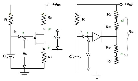
The circuit of UJT relaxation oscillator is shown in the figure 1. It includes 2 resistors R1 and R2 for taking 2 outputs R2 may be some hundred ohms and R1 should be under 50 ohms. The DC source VCC supplies the essential bias. The interbase voltage VBB is difference between VCC and voltage drops across R1 and R2. Generally RBB is much larger than R1 and R2 so that VBB roughly equal to V. Note, RB1 and RB2 are inter-resistance of UJT while R1 and R2 is actual resistor. RB1 is in series with R1 and RB2 is in series with R2 .

Figure 1
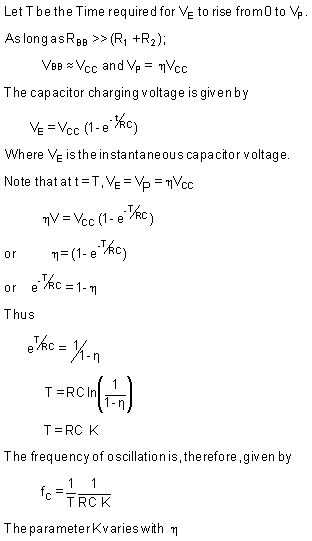
As the power is applied to circuit capacitor begins to charge toward V. The voltage across C, which is VE , rises exponentially with the time constant
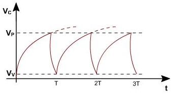
As VE < VP, IE = 0 diode remains reverse biased as long as VE < VP . When capacitor charges up to VP , the diode conducts and RB1 decreases and capacitor begins to discharge. The reduction in R B1 causes capacitor C voltage to drop quickly to the valley voltage VV due to the fast time constant because of the low value of RB1 and R1. As VE drops below Va + VD the diode is no longer forward biased and it thenstops conduction. It now reverts to earlier state and C begins to charge once again toward VCC
The emitter voltage is illustrated in figure2, VE rises exponentially toward VCC but drops to a low value after it reaches VP. The time for VE to drop from VP to VV is small relatively and usually neglected. The period T can thus be approximated as shown below:

Figure 2

Uni-junction transistor
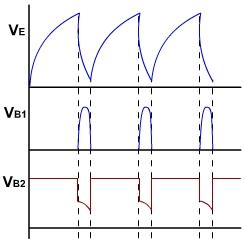
There are 2 additional outputs possible for UJT oscillation one of these is voltage developed at B1 because of capacitor discharge while the other is voltage developed at B2 as shown in the figure 3.
When UJT fires Va drops, causing the corresponding voltage drop at B2. The duration of outputs at B1 and B2 can be determined by C discharge time.
If R1 is small, C discharges quickly and narrow pulse is produced at the output. If R1 = 0, apparently no pulses appear at B1.
If R2 = 0, then no pulse can be generated at B2. If R1 is too large, its positive resistance can swamp negative resistance and prevent UJT from switching back when it has fired.
R2, in addition to giving a source of pulse at B2, is useful for stabilization of temperature of the UJT's peak point voltage.

Figure 3
Email based Electronics Devices and circuits assignment help - homework help at Expertsmind
Are you searching Electronics Engineering assignment help expert for help with UJT Relaxation Oscillator questions? UJT Relaxation Oscillator topic is not easier to learn without any external help? We at www.expertsmind.com offers free lecture notes for Electronics Devices and circuits assignment help and Electronics Devices and circuits homework help. Live tutors are available 24x7 hours for helping students in their UJT Relaxation Oscillator related problems. We provide step by step UJT Relaxation Oscillator question's answers with 100% plagiarism free content. We prepare quality content and notes for UJT Relaxation Oscillator topic under Electronics Devices and circuits theory and study material. These are avail for subscribed users and they can get advantages anytime.
Why Expertsmind for assignment help
- Higher degree holder and experienced experts network
- Punctuality and responsibility of work
- Quality solution with 100% plagiarism free answers
- Time on Delivery
- Privacy of information and details
- Excellence in solving electronics engineering questions in excels and word format.
- Best tutoring assistance 24x7 hours