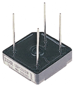
Typical Bridge Rectifier

Although we can use 4 individual power diodes to make a full wave bridge rectifier, pre-made bridge rectifier components are obtainable "off-the-shelf" in the range of different voltage and current sizes which can be soldered directly into a PCB circuit board or be connected by the spade connectors. The image to the right shows a single phase bridge rectifier with the one corner cut off. This cut-off corner indicates that terminal nearest to the corner is positive output terminal or lead with opposite (diagonal) lead being the negative output lead. The other 2 connecting leads are for input alternating voltage from the transformer secondary winding.
Email based Electronics Devices and circuits assignment help - homework help at Expertsmind
Are you searching Electronics Engineering assignment help expert for help with Typical Bridge Rectifier questions? Typical Bridge Rectifier topic is not easier to learn without any external help? We at www.expertsmind.com offers free lecture notes for Electronics Devices and circuits assignment help and Electronics Devices and circuits homework help. Live tutors are available 24x7 hours for helping students in their Typical Bridge Rectifier related problems. We provide step by step Typical Bridge Rectifier question's answers with 100% plagiarism free content. We prepare quality content and notes for Typical Bridge Rectifier topic under Electronics Devices and circuits theory and study material. These are avail for subscribed users and they can get advantages anytime.
Why Expertsmind for assignment help
- Higher degree holder and experienced experts network
- Punctuality and responsibility of work
- Quality solution with 100% plagiarism free answers
- Time on Delivery
- Privacy of information and details
- Excellence in solving electronics engineering questions in excels and word format.
- Best tutoring assistance 24x7 hours