The normalized analog, low pass, Butterworth filter
As a lead-in to digital filter design we look at a simple analog low pass filter - an RC filter, and its frequency response.
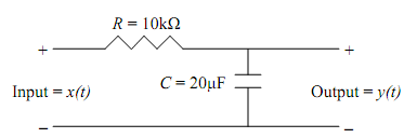
Example: Find the transfer function, Ha(s), impulse response, ha(t), and frequency response, Ha(jΩ), of the following system.

Solution This is a voltage divider. The transfer function is given by

Taking the inverse Laplace transform gives the impulse response,

The frequency response is

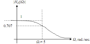
The cut-off frequency is Ωc = 5 rad/sec. The gain at Ω = 0 is 1.

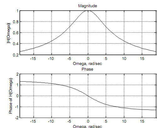
The MATLAB plots of frequency response of Ha(jΩ) = 5 ( jW + 5) are shown below. We use the function fplot. The analog frequency, Omega (Ω), extends from 0 to ∞; however, the plots cover the range 0 to 6π rad/sec.
subplot(2, 1, 1), fplot('abs(5/(5+j*Omega))', [-6*pi, 6*pi], 'k');
xlabel ('Omega, rad/sec'), ylabel('|H(Omega)|'); grid; title ('Magnitude')
%
subplot(2, 1, 2), fplot('angle(5/(5+j*Omega))', [-6*pi, 6*pi], 'k');
xlabel ('Omega, rad/sec'), ylabel('Phase of H(Omega)'); grid; title ('Phase')

If we adjust the values of the components R and C so that 1 RC = 1, we would have Ha(s)= 1/s + 1 which is a normalized filter with cut-off frequency Ωc = 1 rad/sec and gain of 1 at Ω = 0.
Such a normalized LP filter could be transformed to another LP filter with a different cut-off frequency of, say, Ωc = 10 rad/sec by the low pass to low pass transformation s → (s /10). The transfer function then becomes

which still has a dc gain of 1. The gain of this filter could be scaled by a multiplier, say, K, so that

which has a dc gain of K and a cut-off frequency of Ωc = 10 rad/sec.
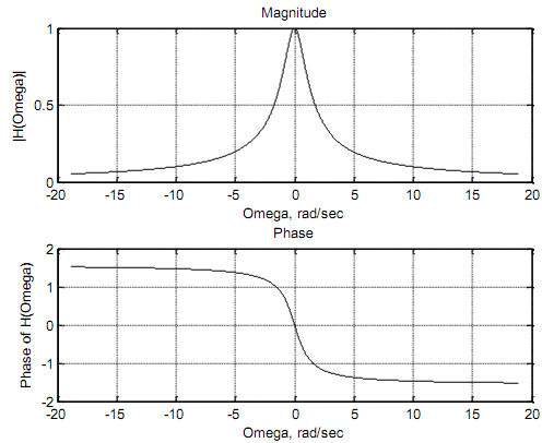
The frequency response of the normalized filter Ha(s) = 1/(s +1) is Ha(jΩ) = 1 ( jW +1) . The
corresponding MATLAB plots are shown below using the function plot. Omega is a vector,
consequently we use "./" instead of "/" etc.
Omega = -6*pi: pi/256: 6*pi; H = 1./(1.+ j .*Omega);
subplot(2, 1, 1), plot(Omega, abs(H), 'k');
xlabel ('Omega, rad/sec'), ylabel('|H(Omega)|'); grid; title ('Magnitude')
subplot(2, 1, 2), plot(Omega, angle(H), 'k');
xlabel ('Omega, rad/sec'), ylabel('Phase of H(Omega)'); grid; title ('Phase')

Email based The normalized analog, low pass, Butterworth filter assignment help - The normalized analog, low pass, Butterworth filter homework help at Expertsmind
Are you finding answers for The normalized analog, low pass, Butterworth filter based questions? Ask The normalized analog, low pass, Butterworth filter questions and get answers from qualified and experienced Digital signal processing tutors anytime from anywhere 24x7. We at www.expertsmind.com offer The normalized analog, low pass, Butterworth filter assignment help -The normalized analog, low pass, Butterworth filter homework help and Digital signal processing problem's solution with step by step procedure.
Why Expertsmind for Digital signal processing assignment help service
1. higher degree holder and experienced tutors
2. Punctuality and responsibility of work
3. Quality solution with 100% plagiarism free answers
4. On Time Delivery
5. Privacy of information and details
6. Excellence in solving Digital signal processing queries in excels and word format.
7. Best tutoring assistance 24x7 hours