The RC Phase Shift Oscillator:
At the low frequencies (around 100 KHz or less), resistors are employed usually to determine the frequency oscillation. Various circuits are used in the feedback circuit including ladder network.
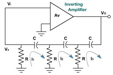
Figure 1
A block diagram of a ladder type RC phase shift oscillation is shown in the figure 1. It consists of 3 resistor R and C capacitors. If phase shift through the amplifier is 180º, then the oscillation may occur at frequency where the RC network produces an additional 180 phase shift.
To find frequency of the oscillation, let us neglect the loading of phase shift network. The KV equations are as follows,
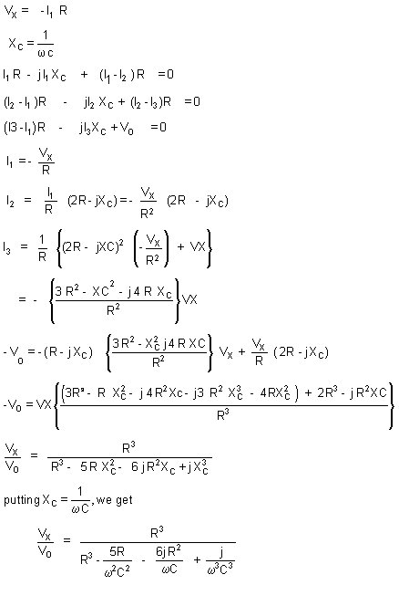
For the phase shift equal to 180 in between Vx and VO, imaginary term of Vx / VO should be zero. Therefore, 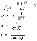
This is frequency of the oscillation. Substituting this frequency in the Vx / VO expression.
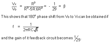
In order to ensure oscillation, initially |Aβ| >1 and under study state Aβ =1. This means that the gain of amplifier should be initially greater than 29 (such that Aβ >1) and under steady stat conditions it decreases to 29.
This oscillator can be realized by using FET amplifier as shown in the figure 2. The feedback circuit is same as above.
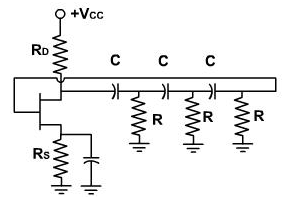
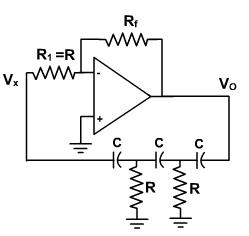
Figure 2 Figure 3
The input impedance of FET is quite high so that there is no loading of feedback circuit. In this circuit, the feedback is voltage series feedback.
Vx =VGS +VS or VGS = Vx - V
The same circuit can be realized using OPAMP. The circuit is shown in the figure 6. The input impedance is high and there is no overloading of feedback circuit. The OPAMP is connected in the inverting configuration and drives 3 cascaded RC sections. The inverting amplifier causes a 180° phase shift in signal passing through it. RC network is used in feedback to provide additional 180° phase shift. Therefore, total phase shift in the signal, of a particular frequency, around loop will be equal to 360° and oscillation will occur at that particular frequency. The gain necessary to overcome the loss in RC network and bring the loop gain up to 1 is supplied by amplifier. The gain can be given as follows

Note that input resistor to the inverting amplifier is also the last resistor of RC feedback network.
Email based Electronics Devices and circuits assignment help - homework help at Expertsmind
Are you searching Electronics Engineering assignment help expert for help with RC Phase Shift Oscillator questions? RC Phase Shift Oscillator topic is not easier to learn without any external help? We at www.expertsmind.com offers free lecture notes for Electronics Devices and circuits assignment help and Electronics Devices and circuits homework help. Live tutors are available 24x7 hours for helping students in their RC Phase Shift Oscillator related problems. We provide step by step RC Phase Shift Oscillator question's answers with 100% plagiarism free content. We prepare quality content and notes for RC Phase Shift Oscillator topic under Electronics Devices and circuits theory and study material. These are avail for subscribed users and they can get advantages anytime.
Why Expertsmind for assignment help
- Higher degree holder and experienced experts network
- Punctuality and responsibility of work
- Quality solution with 100% plagiarism free answers
- Time on Delivery
- Privacy of information and details
- Excellence in solving electronics engineering questions in excels and word format.
- Best tutoring assistance 24x7 hours