Positive Clipper
The clipper which removes positive half cycles of the input voltage is known as positive clipper. The circuit arrangements for the positive clipper are illustrated in figure given below.
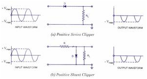
The Positive Series Clipper and Positive Shunt Clipper
The figure shows the positive series clipper circuit (which means that, diode in series with the load). From figure (a) it is seen that while input is positive, diode D is reverse biased and so the output remains at zero i.e., positive half cycle is clipped off. During negative half cycle of the input, the diode is forward biased and so the negative half cycle seems across the output.
Figure (b) shows the positive shunt clipper circuit (which means that diode in parallel with load). From figure (b) it is seen that while the input side is positive, the diode D is forward biased and conducts heavily (which means that, diode behaves as a closed switch). So the voltage drop across diode or across load resistance RL is zero. Hence the output voltage during positive half cycles is zero, as shown in output waveform. During negative half cycles of the input signal voltage, diode D is reverse biased and behaves as an open switch. Consequently the whole input voltage appears across the diode or across the load resistance RL if R is smaller than RL
Actually circuit behaves as a voltage divider with the output voltage of [R L / R+ RL] Vmax = - Vmax when RL >> R
Note: If diode in the figures (a) and (b) is reconnected with reversed polarity, circuits will become for the negative series clipper and negative shunt clipper respectively. Negative series and negative shunt clippers are shown in the figures (a) and (b) as shown below.
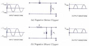
Negative Series Clipper and Negative Shunt Clipper
In discussion above, the diode is considered to be ideal one. If second approximation for diode is considered the barrier potential (0.7 V for silicon and 0.3 V for Germanium) of diode, will be taken into account. Then output waveforms for the positive and negative clippers will be of shape shown in the figure below.
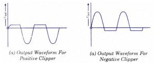
The Output Waveform - Positive Clipper and Negative Clipper
Email based Electronics Devices and circuits assignment help - homework help at Expertsmind
Are you searching Electronics Engineering assignment help expert for help with Positive Clipper questions? Positive Clipper topic is not easier to learn without any external help? We at www.expertsmind.com offers free lecture notes for Electronics Devices and circuits assignment help and Electronics Devices and circuits homework help. Live tutors are available 24x7 hours for helping students in their Positive Clipper related problems. We provide step by step Positive Clipper question's answers with 100% plagiarism free content. We prepare quality content and notes for Positive Clipper topic under Electronics Devices and circuits theory and study material. These are avail for subscribed users and they can get advantages anytime.
Why Expertsmind for assignment help
- Higher degree holder and experienced experts network
- Punctuality and responsibility of work
- Quality solution with 100% plagiarism free answers
- Time on Delivery
- Privacy of information and details
- Excellence in solving electronics engineering questions in excels and word format.
- Best tutoring assistance 24x7 hours