Polyphase structure for a decimator
The decimator block diagram is shown below: it consists of an anti-aliasing filter, H(z), which could be an FIR or an IIR filter, followed by an M-fold down sampler.
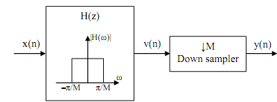
We replace the filter H(z) by its M-component polyphase decomposition

The sub filters P0(zM), P1(zM), ..., PM-1(zM) could be FIR or IIR depending on H(z). The block diagram then appears as below.
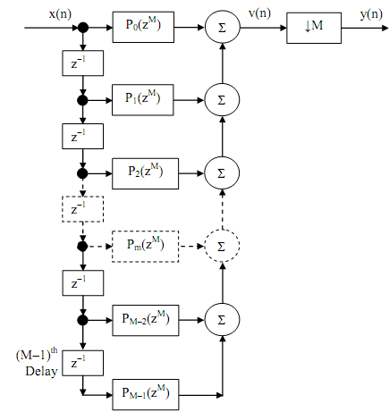
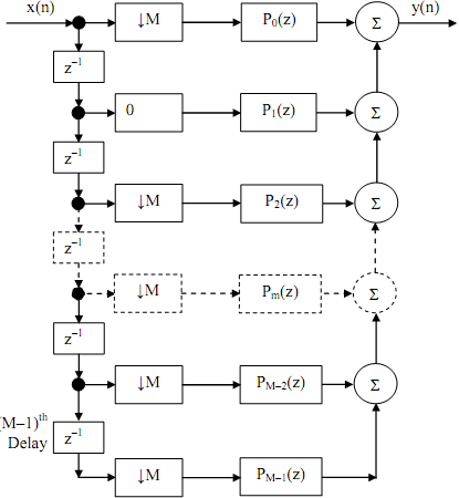
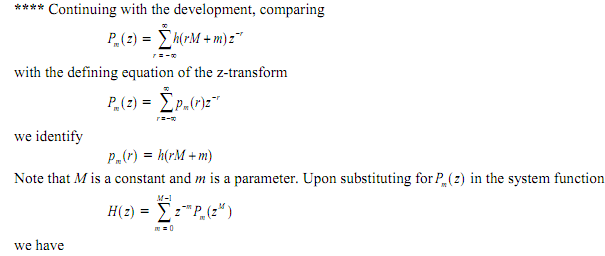
We can use identity #1 to move the down-sampler to the immediate right of Pm (zM) in every branch, and then use identity #3 to change the down-sampler from the immediate right to the immediate left of Pm (.) while at the same time modifing Pm (zM) to m(z). The result seems as below. It may be seen from that diagram that in this structure the number of multiplications is replaced by a factor of M.
Email based Polyphase structure for a decimator assignment help - Polyphase structure for a decimator homework help at Expertsmind
Are you finding answers for Polyphase structure for a decimator based questions? Ask Polyphase structure for a decimator questions and get answers from qualified and experienced Digital signal processing tutors anytime from anywhere 24x7. We at www.expertsmind.com offer Polyphase structure for a decimator assignment help -Polyphase structure for a decimator homework help and Digital signal processing problem's solution with step by step procedure.
Why Expertsmind for Digital signal processing assignment help service
1. higher degree holder and experienced tutors
2. Punctuality and responsibility of work
3. Quality solution with 100% plagiarism free answers
4. On Time Delivery
5. Privacy of information and details
6. Excellence in solving Digital signal processing queries in excels and word format.
7. Best tutoring assistance 24x7 hours