Oscillators:
The oscillator can be described as a source of the alternating voltage. It is different than amplifier.
The amplifier delivers an output signal the waveform of which corresponds to the input signal but the power level of it is higher. The additional power content in output signal is supplied by DC power source used to bias active device.
The amplifier can be thus described as an energy converter; it accepts energy from DC power supply and converts it to energy at signal frequency. Process of energy conversion is controlled by input signal, thus if there is no input signal, no energy conversion occurs and there is no output signal.
The oscillator alternatively requires no external signal to initiate or maintain the process of energy conversion. Instead an output signals are produced as long the source of DC power is connected. Figure 1, shows block diagram of the amplifier and the oscillator.
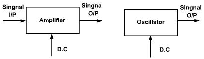
Figure 1
Oscillators can be classified in the terms of their output waveform, components, frequency range, or circuit configuration.
If the output waveform is sinusoidal in nature, it is called as harmonic oscillator otherwise it is called as relaxation oscillator, which include triangular, square, and saw tooth waveforms.
Oscillators employ active and passive components both. The active components gives energy conversion mechanism. The active devices are transistor, FET etc.
The passive components generally determine frequency of the oscillation. They also influence the stability, which is a measure of change in the output frequency with time, temperature or other factors. The passive devices can include resistors, capacitors, inductors, transformers, and resonant crystals.
The capacitors used in the oscillator's circuits should be of good quality. Because of the low losses and superb stability, silver mica or ceramic capacitors are usually preferred.
The elementary sinusoidal oscillator is shown in the figure 2. The inductor and capacitors are reactive elements that are they are capable of storing the energy. The capacitor stores energy in its electric field. Whenever there is voltage across its plates and inductor stores energy in the magnetic field of it whenever current flows through it. Both the C and L are assumed to be loss less. The energy can be introduced into circuit by charging capacitor with the voltage V as shown in the figure 2. As long as switch S is open, C cannot discharge and hence i=0 and V=0.
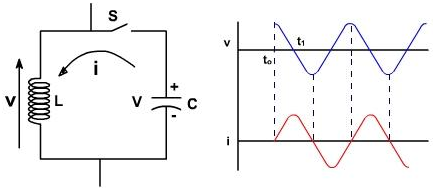
Figure 2
S is closed at t = to, This means that the V rises from 0 to V, Just before closing the inductor current was zero and inductor current can't be changed instantaneously. The current increases from zero value sinusoidally and is given as follows
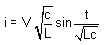
The capacitor losses its charge and energy is simply transferred from capacitor to the inductor magnetic field. The total energy is same still. At t = t1, all the charge has been removed from the capacitor plates and voltage reduces to zero and at current reaches to its maximum value. The current for t> t1 charges C in opposite direction and the current decreases. Thus LC oscillation takes places. Both the voltage and current are sinusoidal though no sinusoidal input was applied. The frequency of the oscillation is 
The circuit which is discussed is not a practical oscillator because even though loss less components was available, one could not extract energy without introducing the equivalent resistance. This would result in the damped oscillations as shown in the figure 3.
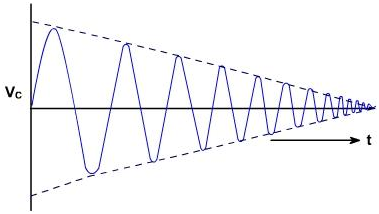
Figure 3
These oscillations become zero as soon as the energy in tank is consumed. If we remove too much power from circuit, the energy can be completely consumed before t he first cycle of oscillations can occur yielding the over damped response.
It is possible to supply the energy to tank to make up for all the losses, thus maintaining oscillations of the constant amplitude.
Since the energy lost can be related to a positive resistance, it follows that circuit would gain energy if the equivalent negative resistance were available. The negative resistance, supplies whatever energy the circuit lose because of positive resistance. Some of the devices exhibit negative resistance characteristics, an increasing current for the decreasing voltage. The energy supplied by negative resistance to circuit, actually comes from the DC source which is necessary to bias the device in the negative resistance region of it.
Another technique for producing the oscillation is to use the positive feedback considers an amplifier with the input signal vin and output vO as shown in the figure 4.
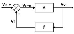
Figure 4
Amplifier is inverting amplifier and can be transistorized, or FET or OPAMP. The output is 180° out of phase with input signal vO=-Avin.(A is negative)
Now the feedback circuit is added. The output voltage is fed to feedback circuit. The output of the feedback circuit is 180° phase shifted and also gets attenuated. Therefore the output from the feedback network is in phase with the input signal vin and it can be made equal to input signal also.
The Vf can be connected directly if this is so, and externally applied signal can be removed and the circuit will continue to generate the output signal. The amplifier has an input still but the input is derived from output amplifier. The output essentially feeds on itself and is regenerated continuously. This is the positive feedback. The overall amplification from vin to vf is 1 and the whole phase shift is zero. Hence the loop gain A β is equal to unity.

When this is satisfied then the closed loop gain is infinite. That is an output is produced without any external input.
vO = A verror
= A (v in + v f )
= A (vin + β vO)
or (1-A β )vO = A vin
or 
When A β = 1, vO / vin= ∞
The criterion A β = 1 can be satisfied only at one frequency. This is called as backhausen criterion. The frequency at which the sinusoidal oscillator will operate is frequency for which the total phase shift introduced, as signal proceeds from input terminals, through amplifier and feedback network and back again to input is precisely zero or an integral multiple of 2p. Thus frequency of the oscillation can be determined by the condition that the loop phase shift is zero.
The oscillation will not be sustained, if at the oscillator frequency, A β <1 or A β>1. Figure 5 show the output for the two different contains A β < 1 and A β >1.
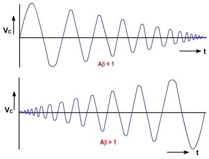
Figure 5
If Aβ is less than unity then Aβ vin is less than vin, and the output signal will die out, when the externally applied source is removed. If the value of Aβ>1 then A b vinis greater than vin and output voltage builds up gradually. If A β = 1, only then output voltage is sine wave under steady state conditions.
In a practical oscillator, it is not required to supply a signal to begin the oscillations. Instead, the oscillations are self-starting and begin as soon as the power is applied. This is possible due to electrical noise present in all the passive components.
Thus, as soon as the power is applied, there exists already some energy in circuit at fo, the frequency for which the circuit is designed to oscillate. This energy is quite small and is mixed with all other frequency components also present, but it is there. At this frequency only the loop gain is slightly greater than unity and the loop phase shift is zero. At all other entire frequency Barkhausen criterion is not satisfied at all. The magnitude of the frequency component fo is made a little higher each time it goes around the loop. Soon the fo component is much larger than all the other components and ultimately its amplitude is limited by circuits own non-lineareties (reduction of gain at the high current levels, saturation or cut off). Thus the loop gain decreases to unity and steady stage is reached. If it does not, then the clipping can take place.
Practically, Aβ is made greater than unity. So that due to disturbance the output does not change but if Aβ = 1 and due to some reasons if Aβ decreases slightly than the oscillation may die out and oscillator stop functioning. In conclusion, all practical oscillations involve:
- Active device to supply the loop gain and negative resistance.
- Frequency selective network to determine frequency of the oscillation.
- Some type of non-linearity to limit amplitude of oscillations.
Email based Electronics Devices and circuits assignment help - homework help at Expertsmind
Are you searching Electronics Engineering assignment help expert for help with Oscillators questions? Oscillators topic is not easier to learn without any external help? We at www.expertsmind.com offers free lecture notes for Electronics Devices and circuits assignment help and Electronics Devices and circuits homework help. Live tutors are available 24x7 hours for helping students in their Oscillators related problems. We provide step by step Oscillators question's answers with 100% plagiarism free content. We prepare quality content and notes for Oscillators topic under Electronics Devices and circuits theory and study material. These are avail for subscribed users and they can get advantages anytime.
Why Expertsmind for assignment help
- Higher degree holder and experienced experts network
- Punctuality and responsibility of work
- Quality solution with 100% plagiarism free answers
- Time on Delivery
- Privacy of information and details
- Excellence in solving electronics engineering questions in excels and word format.
- Best tutoring assistance 24x7 hours