Monostable Multivibrator
The monostable multivibrator (called a ONE-SHOT MULTIVIBRATOR) is a square- or rectangular-wave generator with only one stable condition. With no input signal one amplifier conducts and other is in cutoff. The monostable multivibrator is usually used for pulse stretching. It is used in the computer logic systems and communication navigation equipment. The operation of monostable multivibrator is simple relatively. The output changes from one voltage level to different voltage level. The output remains at this voltage level for a certain period of time. Then the circuit reverts automatically to its original condition and remains that way until another the trigger pulse is applied to input.
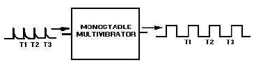
Figure 3-10.-Monostable multivibrator block diagram.
The digram for the monostable multivibrator is shown in the figure 3-11. Like astable multivibrator, 1 transistor conducts and the other cuts off when the circuit is provided current.
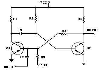
Figure 3-11.-Monostable multivibrator schematic.
Recall that when astable multivibrator was energized 1st, it was not possible to predict which transistor would initially go to cutoff due to circuit symmetry. The one-shot circuit is not symmetrical like astable multivibrator. Positive voltage VBB can be applied through R5 to base of Q1. This positive voltage makes Q1 to cut off. Transistor Q2 saturates because of the negative V voltage applied from CC to its base through R2. The circuit is illustrated in its stable state.
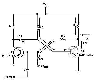
Figure 3-12.-Monostable multivibrator (stable state).
Let's take detailed look at the circuit conditions in this stable state (figure 3-12). As stated above, Q1 is cut off, so no current flows through R1, and collector of Q1 V is at CC. Q2 is saturated and has no voltage drop across it practically, so its collector is essentially at 0 volts. R5 and R3 form a voltage divider from VBB to ground potential at the collector of Q2. The tie point between these 2 resistors will be positive. Therefore, the base of Q1 is held positive, ensuring that Q1 remains cutoff. Q2 will remain saturated as the base of Q2 is slightly negative as a result of the Vcc voltage drop across R2. If collector of Q1 is near CC and base of Q2 is near ground, C1 should be charged to nearly VCC volts with polarity shown. Now that all components and voltages have been described for the stable state, let us see how the circuit operates (see figure 3-13).
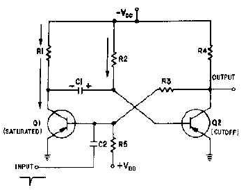
Figure 3-13.-Monostable multivibrator (triggered).
The one-shot multivibrator has now been turned on by applying a pulse at the input. It will turn itself off after some time. To see how it does this, look at the figure 3-13 again. Q1 is held in saturation by negative voltage applied through R3 to its base, so the circuit can't be turned off here. Notice that base of Q2 is connected to C1. The positive charge on C1 keeps Q2 cutoff. Remember that a positive voltage change was coupled from the collector of Q1 when it began conducting to the base of Q2, placing Q2 in cutoff.
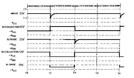
Figure 3-14.-Waveforms of a monostable multivibrator (triggered).
The part of the operation not described till now is the short C1 charge time which occurs right after Q1 and Q2 return to their stable states. This is the time required for C1 to gain electrons on its left side. This charge time can be determined by the R1C1 time constant.
Another version of monostable multivibrator is shown in figure 3-15. See (A) is the circuit and see (B) shows related waveforms. In the stable condition (T0), Q1 is cut off and Q2 is conducting. The input trigger (positive pulse at T1) is applied to the collector of Q1 and coupled by C1 to the base of Q2 making Q2 to be cut off. V The collector voltage of Q2 then goes CC. The negative voltage at the collector of Q2 forward biases Q1 through R4. With the forward bias, Q1 conducts, and the collector voltage of Q1 goes to nearly 0 volts. C1 discharges now and makes Q2 cut off. Q2 remains cut off until C1 discharges sufficiently to allow Q2 to conduct again (T2). When Q2 conducts again, the collector voltage of it goes toward 0 volts and Q1 is cut off. The circuit returns to the quiescent state of it and has completed a cycle. The circuit remains in the stable state till the next trigger arrives (T3).
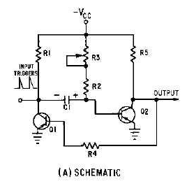
Figure 3-15A.-Monostable miltivibrator and waveshapes. Schematic.
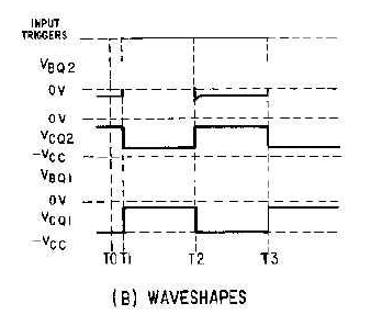
3-14 Figure 3-15B.-Monostable miltivibrator and waveshapes. Waveshapes
Note that R3 is variable to permit adjustment of the gate width. Increasing R3 increases the time of discharge for C1 which increases cutoff time for Q2. Increasing the value of R3 broadens the gate. To decrease the width of gate, reduce the value of R3. Figure 3-16 shows relationships in between the output signal and the trigger. View (A) of the figure shows the input trigger; views (B) and (C) show the different gate widths made available by R3. Although the durations of gates are different, the duration of complete cycle remains the same as the pulse repetition time of the triggers. See (D) of the figure illustrates that the trailing edge of the positive alternation is variable in nature.
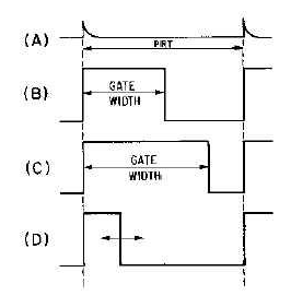
Figure 3-16.-Monostable multivibrator waveforms with a variable gate.
The reason monostable multivibrator is also known as one-shot multivibrator can easily be seen. For every trigger pulse applied to multivibrator, a complete cycle, or a positive and negative alternation of output, is completed.
Email based Electronics Devices and circuits assignment help - homework help at Expertsmind
Are you searching Electronics Engineering assignment help expert for help with Monostable Multivibrator questions? Monostable Multivibrator topic is not easier to learn without any external help? We at www.expertsmind.com offers free lecture notes for Electronics Devices and circuits assignment help and Electronics Devices and circuits homework help. Live tutors are available 24x7 hours for helping students in their Monostable Multivibrator related problems. We provide step by step Monostable Multivibrator question's answers with 100% plagiarism free content. We prepare quality content and notes for Monostable Multivibrator topic under Electronics Devices and circuits theory and study material. These are avail for subscribed users and they can get advantages anytime.
Why Expertsmind for assignment help
- Higher degree holder and experienced experts network
- Punctuality and responsibility of work
- Quality solution with 100% plagiarism free answers
- Time on Delivery
- Privacy of information and details
- Excellence in solving electronics engineering questions in excels and word format.
- Best tutoring assistance 24x7 hours